This modification was inspired by an article on BoltRC’s blog about replacing the Taranis’ in-built antenna with an SMA jack, which then allows connecting different, higher gain, antennas.
With the BoltRC mod, I didn’t like the idea of hot melt glue holding the SMA connector in place, and the method documented below has the SMA jack rigidly mounted through the radio’s shell.
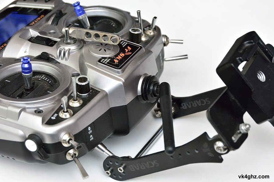
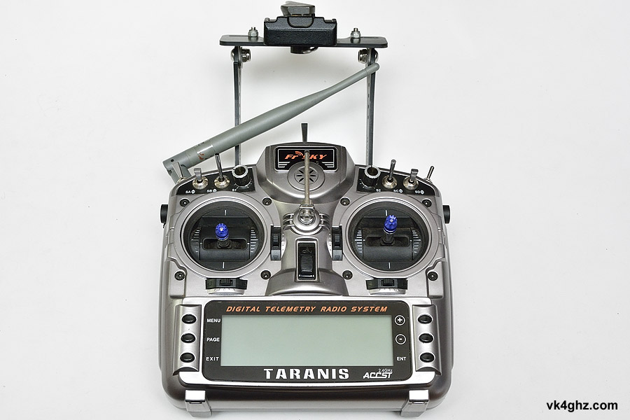
If I’m not flying FPV with goggles, my Taranis radio accommodates a 7″ 5.8 GHz diversity screen.
This is by way of a Manfrotto Quick Release mount, so my antenna placement has to take this into account.
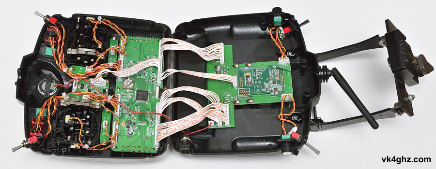
Remove the Philips heads screws and split the radio’s shell apart like so:
Internal antenna is terminated on the RF board:
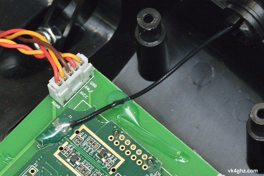
Peel off the hot melt glue with a finger nail, and/or carefully pluck it off using small side cutters:
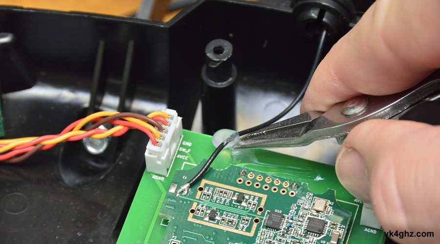
De-solder the coax tail from the PCB.
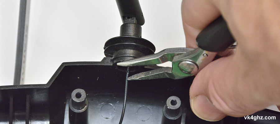
Remove the internal antenna by clamping down on the locating tabs, and pull it out:
Now to go about fitting an SMA connector with a coax tail.
You can purchase a kit from BoltRC: http://boltrc.com/index.php?route=product/product&path=75_105&product_id=567
Or, if you’re like me and already have RG316 coax, and plenty of various bulkhead mount SMA jacks on hand, you don’t need to buy anything extra.
Here I’m using a SMA RP jack from RF Shop, located in Oxley (Brisbane) – my favorite local shop for when I want connectors RIGHT NOW!
http://rfshop.com.au/sma-connector-rg316-rp-male-pin-with-sealing-ring-sma9105-0316.html
Datasheet www.jyebao.com.tw/download.php?pdf_path=SMA9105-0316.pdf
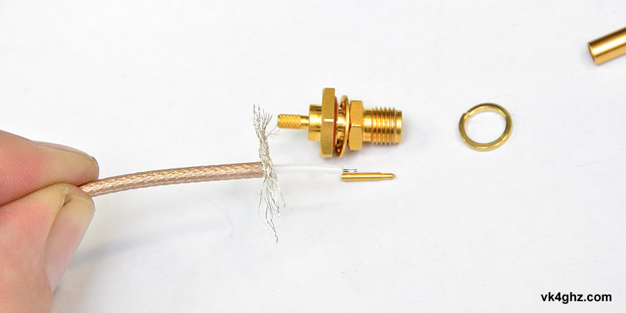
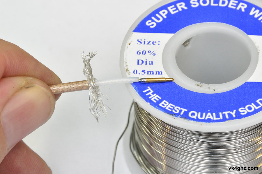
Prepare the RG316 to solder to the center pin.
I find it easier to work with SMA inner pins if they are held in place, like sitting in the hole of these old wire strippers:
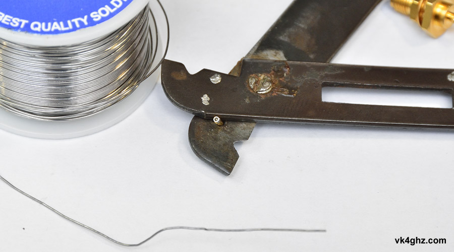
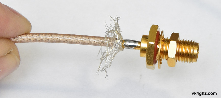
Center pin is soldered:
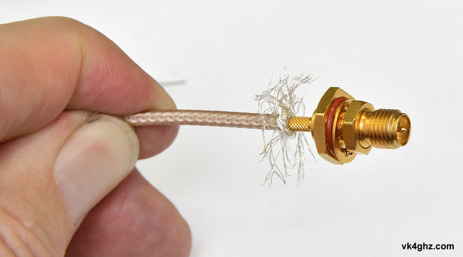
Slide connector body over:
We sure as hell do not crimp connectors being used at 2.4 GHz!
Tinned with solder:
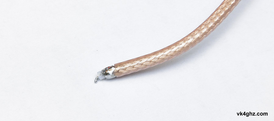
Outer braid is given a haircut with small scissors so the braid is the correct length, and then sweat soldered around the connector:
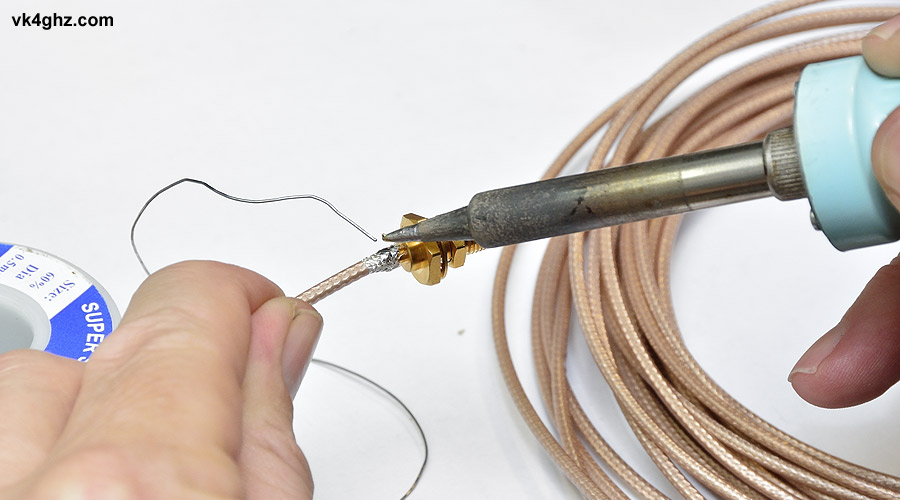
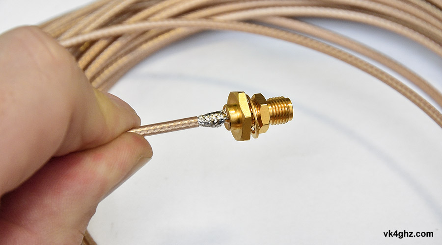
Finished result.
I didn’t bother putting any heat shrink around it to pretty it up… why bother, it’s inside the damn radio!
This where I differ from the BoltRC mounting method, where it’s a very loose fit inside the old antenna hole, and “secured” with hot met glue.
The SMA jack is actually a nice tight, robust, fit in a switch hole.
SMA mounts where switch ‘SF’ was. This provides for a nice short coax tail. (Read as: minimal loss @ 2.4 GHz).
Determine how much RG316 is needed, and cut accordingly.
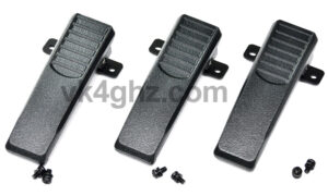
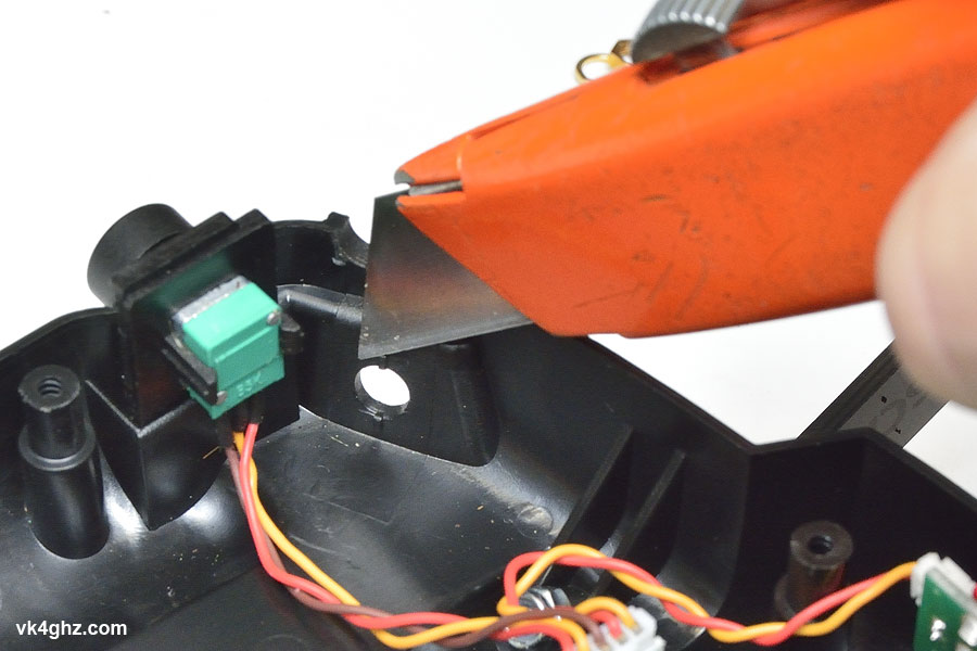
Two small switch locking tabs need to be removed from the shell so the SMA will sit flush against the shell:
Using switch ‘SE’ position is problematic, due to the hole being split in half with the case shell.
Switch ‘SF’ now needs to be relocated. To avoid drilling any holes, guess where?

So why wasn’t the SMA mounted in the old antenna hole?
• threaded neck of the SMA wasn’t long enough
• antenna would be annoying in front of the 7″ screen when in use
• screen would tend to mask the antenna, negating any extra gain we may achieve
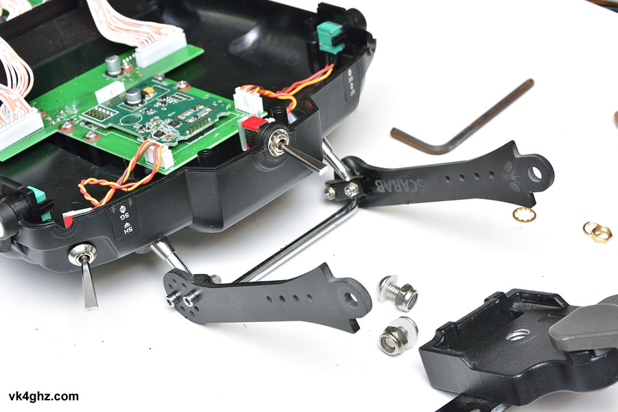
Toggle switch threaded bush is long enough to fit through the thick shell casing here (unlike the SMA).
Only two star washers required:

With the switch relocated, we can finish off the SMA connector tail.
RG316 is pre-prepared for soldering to the small PCB pads. Outer braid is tinned, and inner is formed to meet the PCB surface:
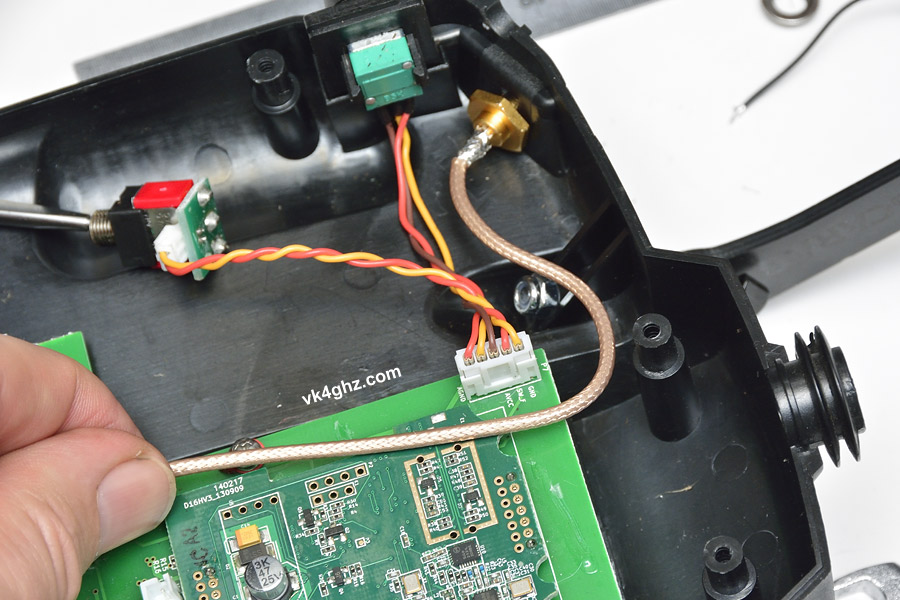
Soldered to the PCB. Clean away any flux residue for a clean finish:

With the SMA connector securely fastened, re-assemble radio.
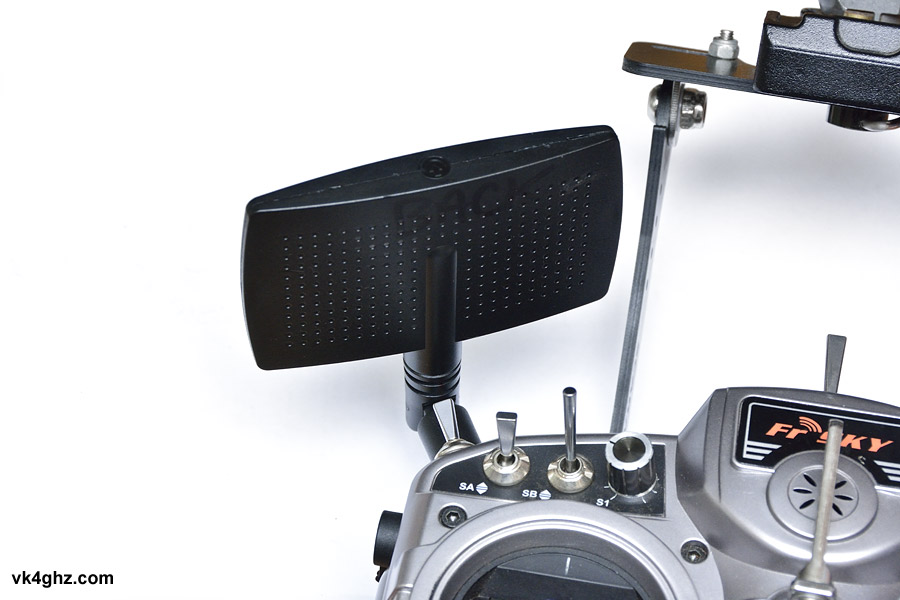
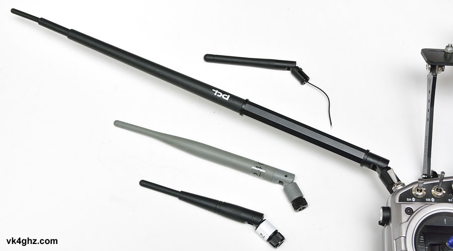
Now you have a wider selection of antennas to use. Seen here compared to the stock antenna that was removed:
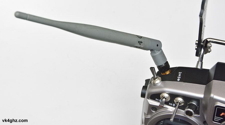
In this case, even a larger antenna folds in nicely, and is protected from knocks and bumps by the screen mount:
It’s handy having SWR on one of the telemetry pages so an SWR check can be made on each antenna:
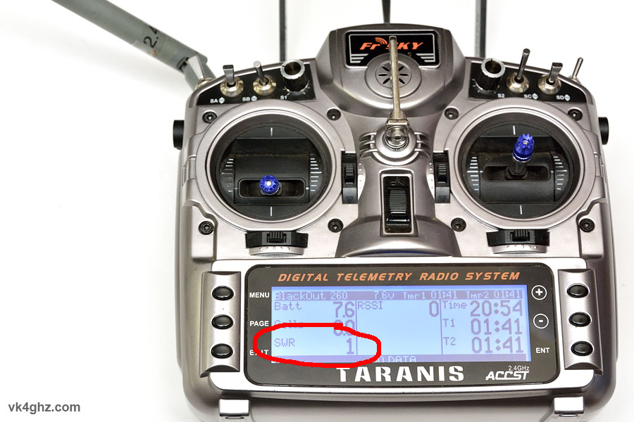
This is a relative number, not an absolute measurement of anything (Standing Wave Ratio is a ratio anyway), but we want the lowest number, preferably as close to zero as possible.
If you power up and forget to connect an antenna, don’t worry, Taranis will let you know about it!

From an afternoon of field use, I found that the patch antenna was the best all-round performer, and offered a surprisingly wide angle of coverage.

🙂