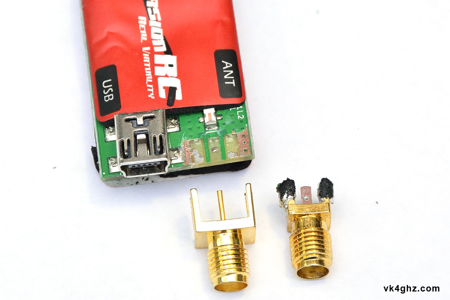
Ripped the SMA antenna connector off your EzUHF receiver in a crash?
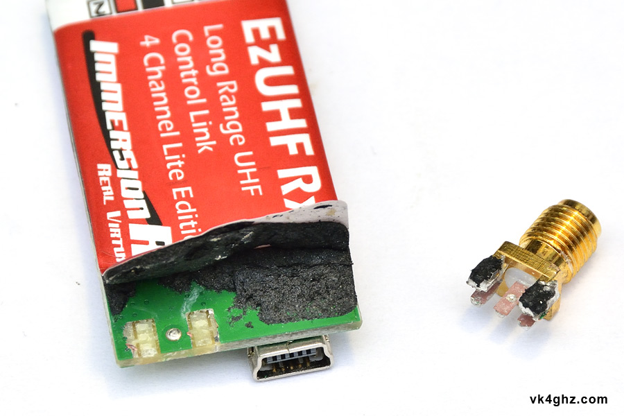
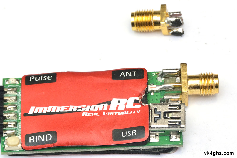
It probably looks like this on the solder side:
Components side:
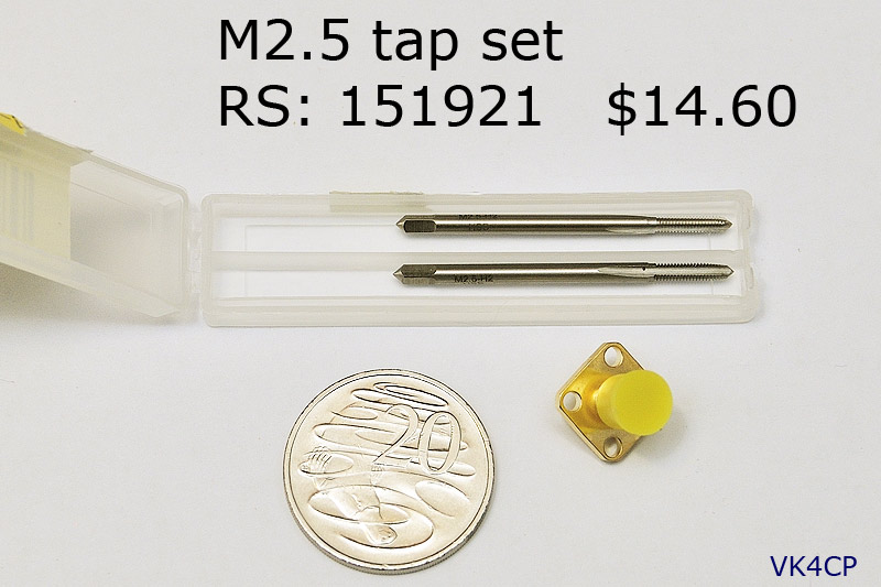
Whilst the SMA jack fitted on this receiver has a narrow body, all is not lost, as you can most likely fit a wide body SMA jack in its place:

When purchasing PCB mount SMA “end launch” style connectors, be aware of the PCB thickness the connector is designed for.
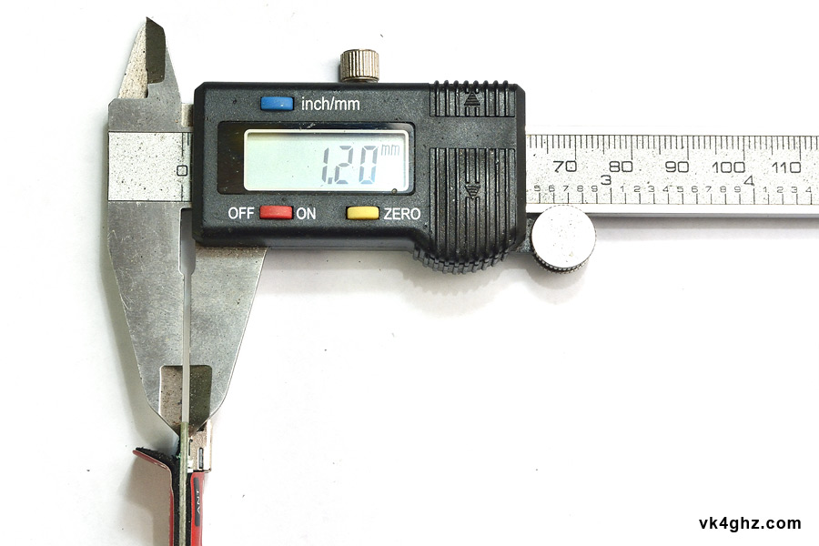
EzUHF PCB measures 1.2mm, but you can easily fit a common SMA jack intended for standard 1.6mm PCBs.
I get a lot of connectors, RG316 coax, etc from RF Supplier in Shenzen, China.
http://www.rfsupplier.com/launch-jack-mount-wide-flange-short-version-p-684.html
With a wide body connector, it becomes a straight-forward process to remove some of the PCB solder mask (ie: the green stuff) to reveal the copper to which you can solder to:
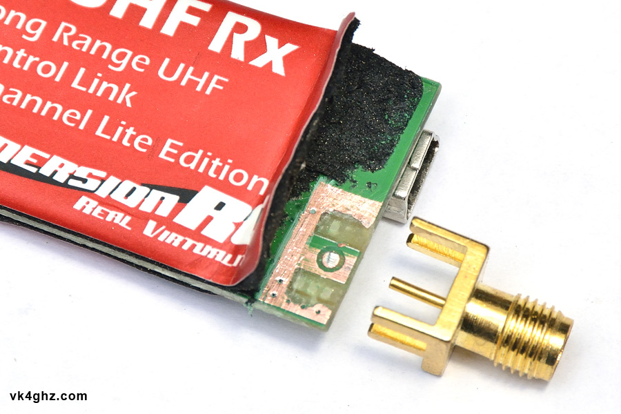
Using a Stanley knife, lightly and carefully, scrape the solder mask away.
Be careful not to gouge the copper underneath the thin mask layer.
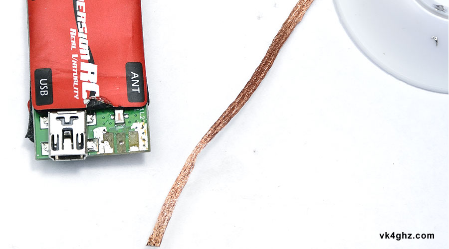
Once you have tinned both sides of the copper, clean up with some solder wick, so the PCB has an even flat tin applied to it.
(Seen here before the wick is used)
Other side, after PCB tinning has been cleaned up:
Here we see how scraping away solder mask and fitting a wide body SMA works:
(Note that we don’t need to scrape away the solder mask in the center – I just got a bit carried away!)

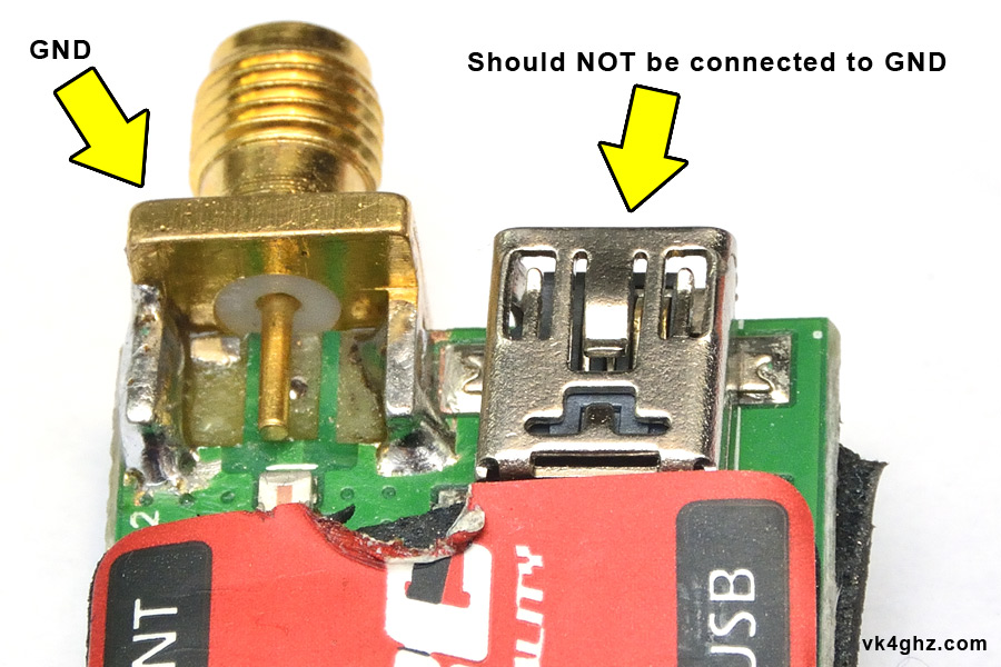
On the components side, be aware that body of the mini USB jack is not connected to ground, for some odd reason.
Be careful not to short the left hand mini USB mounting tab to the new copper area you have made:
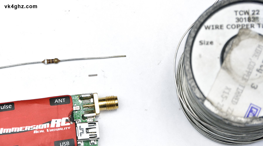
To connect the centre pin you can use some small gauge TCW (Tinned Copper Wire), or even the last few millimeters of a component’s leg, such as a resistor:
Here we see the finished job, and you will see the small length of TCW connecting to the middle pin of the SMA.
Original narrow-body SMA jack has now been replaced with a wide-body SMA jack – easy!
🙂
