To increase 5.8 GHz FPV range and minimise receiver dropouts, a broadband microwave LNA (Low Noise Amplifier) is assembled and tested.
Whilst you could use a gain antenna like a helix, or quad patch antenna, extra antenna gain comes at the tradeoff of directivity.
The object here is keep using omni directional antnnas, whilst achieving more receiver gain.
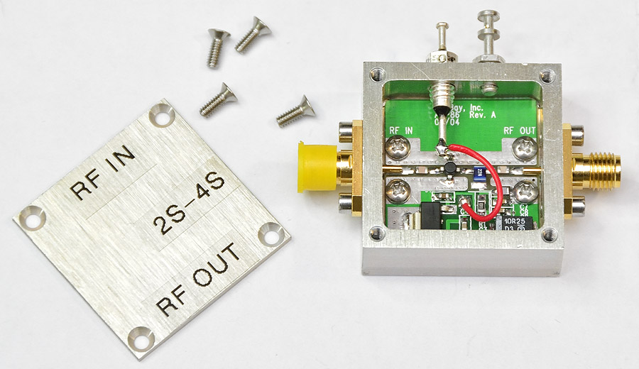
EBayer ‘RF Extra‘ has various “designer kits’ which include the 1″ x 1” PCB, SMA connectors, hardware (American 2-56 threads), a 78M08 regulator, and some kits include a nicely milled enclosure to suit.
What you see in the picture is typical of what you get:

In addition to this you will need the capacitors, resistors, the voltage regulator, and an inductor.
This particular kit is designed to take a SOT-86 MMIC (Monolithic Microwave Integrated Circuit), which is the same a ‘Micro-X’ package.
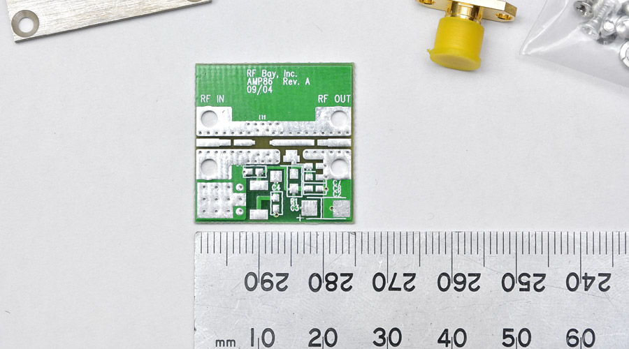
SMD components used on this board get as small as 0603. Have a look at the pads for C2, C8, C7:
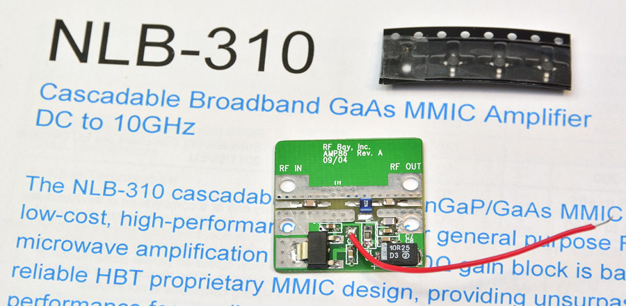
The MMIC chosen for this project was an NLB-310 from RF Micro Devices.
Why?
Only because several were on hand already, as you do, and they’re good up to 10 GHz.
Gain @ 2.4 GHz is ~12dB, falling off to ~10dB @ 5.8 GHz.
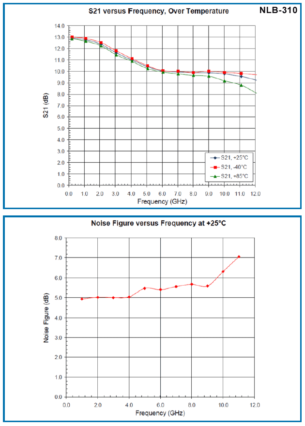
Noise figure isn’t that impressive at all, being 5 ~ 5.5dB. 🙁
The RF Extra kit did come with a standard 78M08 (8V reg, 2V dropout) in a DPAK, but this regulator would start to drop regulation with a battery volts of 10V.
The ability to run this off a 2S LiPo is desirable, so a 78M05 in a SOT-223 was fitted instead so battery volts can get as low as 7V.
To fit a SOT-223 to the DPAK pads, the middle GND pin of the 78M05 was carefully fatigued off with small pliers.
This pin is unnecessary anyway, as the rear tab is also GND.
First thing to do is round-off the PCB’s corners, so it drops into the enclosure.
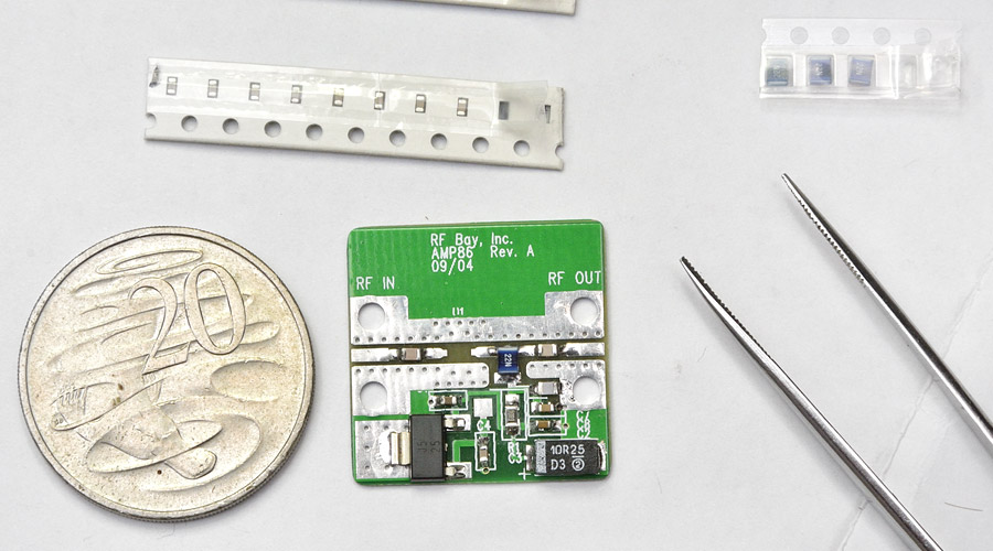
The 20c coin gives you an idea of how small 0603 components are, and the soldering skills that are required!
In the image below, everything but the MMIC has been fitted. That tantalum capacitor on the bottom-right is a ‘Case C’ and the regulator is a SOT-223 78M05 (5V reg).
Once you solder a MMIC to a PCB, they’re difficult, nigh impossible, to remove again without damaging.
Before the MMIC is fitted, the +5v rail is checked to be ok by temporarily hooking the board up to a 12V power supply.
With the MMIC fitted, and it’s operating current checked (50mA), the board is inserted into the enclosure and bolted in.
SMA connectors fitted, and soldered to the board. Then fit the feed-through capacitor and GND lug, and lastly solder up the one and only wire for the +ve feed:

All up weight of the LNA with SMA adapter but without power lead:
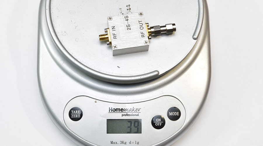
Not particularly heavy, and it was envisaged this could be inserted in-line with the antenna on top of a pair of FPV googles or headset.
See why we might want it to work off a 2S battery… thinking Fatshark etc battery. 😉
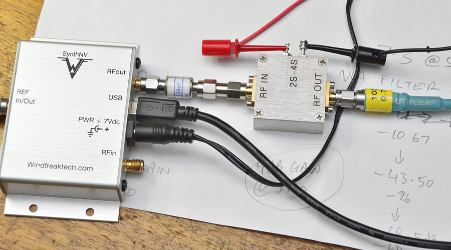
Next thing to do was some gain measurements, and with the LNA being a broadband device (no bandpass filtering on the front end), it will also work at 2.4 GHz.
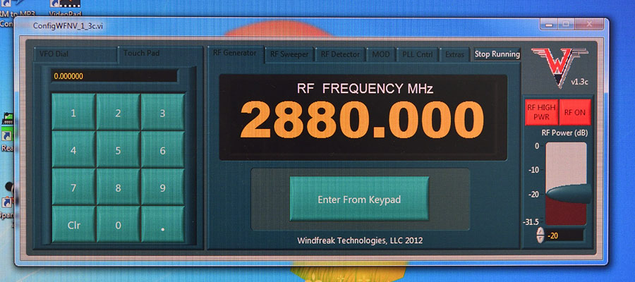
Signal generator here is a Windfreak SynthNV.
The SynthNV’s ouptut level was turned down low, and you’ll note there is also a 26dB attenuator on it’s output as well:
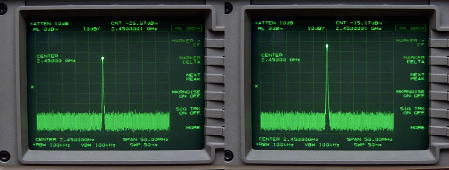
First gain test is on 2.4 GHz, and SynthNV is directly set to 2450 MHz:
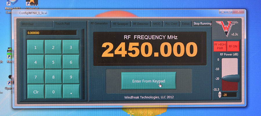
Left: LNA not in circuit (-26.67dBm), right: LNA in-line (-15.17dBm). We can see 11.5dB gain @ 2.4 GHz:
The SynthNV only operates up to 4.4 GHz, so for a 5.8 GHz test it’s set to 2880 MHz, and we will use the second harmonic @ 5760, albeit at a lower level:
Left: LNA not in circuit (-59.33dBm), right: LNA in-line (-50.33dBm) We can see 9dB gain @ 5.8 GHz:
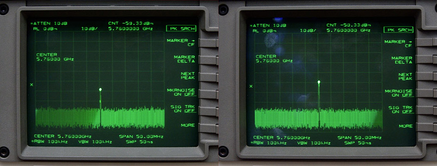
These results are close to what the NLB-310 datasheet suggests.
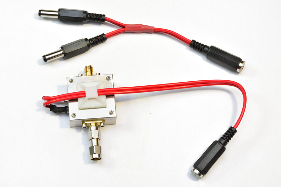
Wired up for the real-world using 2.1mm DC connectors, with a Y-adapter:
I currently fly FPV using a 5.8 GHz 7″ screen that has twin (diversity) receivers:
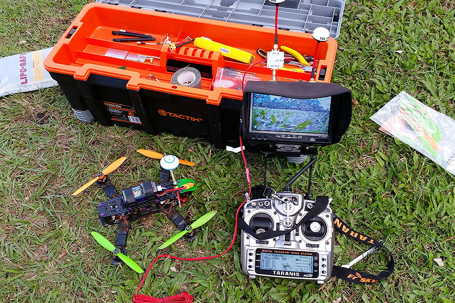
Identical Fatshark cloverleaf omnis on both antenna ports.
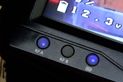
The screen indicates which receiver is being used at any instant in time:
Having flown with this arrangement several times now (5.8 GHz), the receiver spends most of it’s time using the antenna port that has the LNA in-line, and there is a marginal improvement with range and less drop outs.
A friend who flys using 2.4 GHz FPV, but with a single antenna port, also noted a marginal improvement when flying the same circuit with & without the LNA.
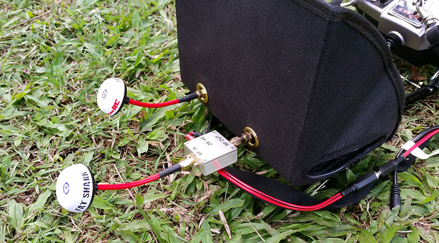
Whether it be a screen or goggles, you can see the how easily an LNA connects in-line:
Simply stating ‘9dB of gain’ sounds like a lot, but the actual improvement in sensitivity is far less than this, largely due to the NLB-310’s high noise figure. In hindsight, a front-end device with a ~ 5dB NF was a poor choice, but was conveniently on hand at the time.
The front-end noise figure of the Chinese made screen itself is unknown, and I don’t have the ability to quantify it.
If all the parameters were known, the overall sensitivity improvement an LNA could offer could be calculated on paper, even before constructing something, but we’re dealing with consumer hobby R/C gear with dumbed-down specifications and no schematic diagrams.
The whole point of this exercise was to do some real world flight tests to determine if the LNA was worthwhile, or not.
Since constructing this LNA, another MMIC has been found with significantly more gain, and a 3dB+ better noise figure:
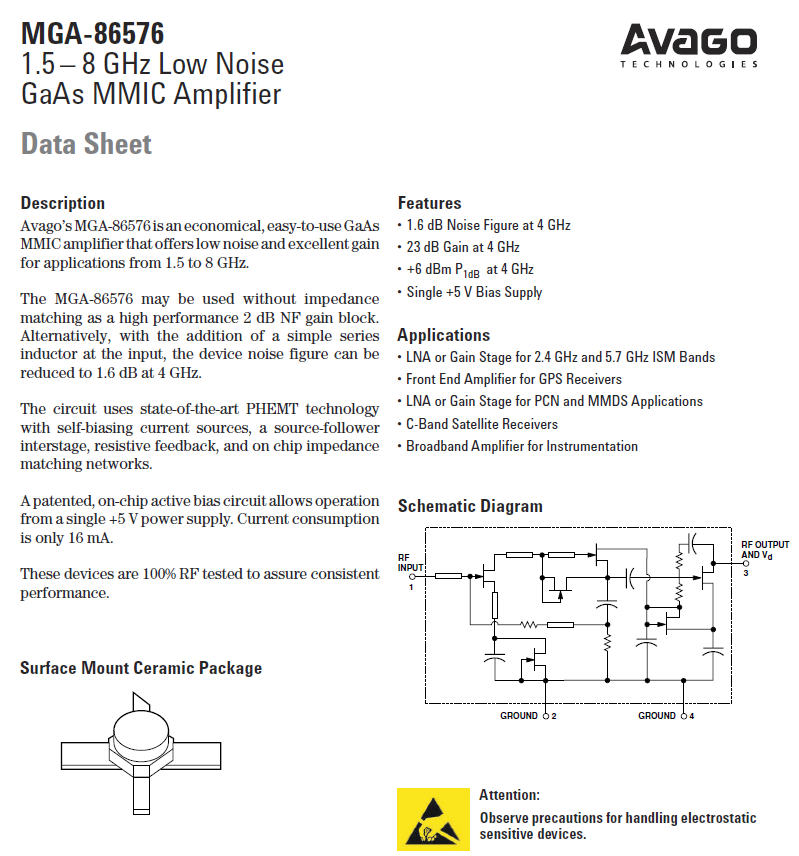
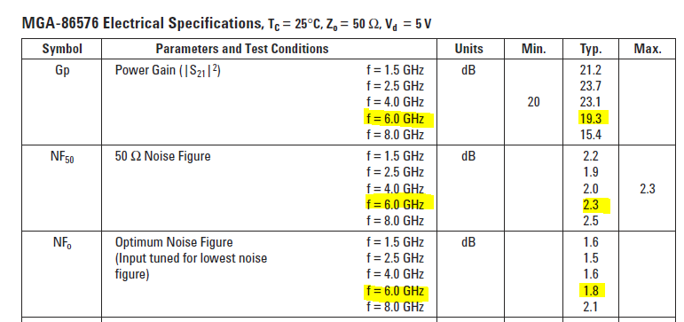
Needless to say, some MGA-86576 MMICs have been ordered, along with another PCB & milled enclosure kit, and even a PCB for a 2-stage LNA to experiment with!
Some more real-world practical experimentation will soon reveal how much improvement a small in-line LNA offers, and how useful something like this might be with FPV flying.
🙂