What does the ThunderBolt Commander do?
ThunderBolt Commander can send four pre-defined command packets to a Trimble ThunderBolt Disciplined Clock.
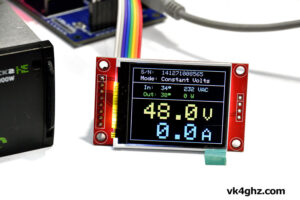
Primarily, it is used to change the ThunderBolt’s receiver mode between OverDet Clock and Full Position 3D.
Watch the video
Easy to build on Veroboard

Do I need this?
If you always operate a Trimble ThunderBolt Disciplined Clock fitted with a ThunderBolt Display in a static location, no. It does not matter that the ThunderBolt will not update your lat/lon since the last survey.
If you operate your ThunderBolt in different locations, ie; as a portable station or as a Rover, then this would be very handy, and saves having to use a PC/laptop to change the ThunderBolt’s operating mode.
Background
I discovered when mobile with the ThunderBolt, latitude/longitude does not update when the ThunderBolt is in it’s default OverDetermined Clock mode. At home, this is something you might remain oblivious to.
Whilst OverDetermined Clock mode is the optimum mode for Time-only fixes, important for disciplining it’s internal 10MHz oscillator to the best accuracy, it is does not report position. I have tried setting my ThunderBolt to Full Pos 3D with [i]TBoltmon.exe[/i] and saved the “Receiver Segment” in EEPROM, but annoyingly, it keeps powering up in OverDet mode.
Of course, this is no problem if you’re in a static location, ie; at home in the shack, or being the time reference in a CDMA base station! If you’re a rover, or on the move, then this might be a hassle.
How Do I get a ThunderBolt Commander?
Turn on the soldering iron, because you make it!
A ThunderBolt Commander costs about $15 to construct, but you may already have some of the parts.
It is based on a cheap 8-pin PICAXE, the PICAXE 08M2.
This part is obtainable in Australia from the PICAXE distributor, Wiltronics. With postage costs, it may be a good idea to buy several of them in one hit, or get a few others together for a group buy.
Altronics also list the PICAXE 08M2 as a stock item.
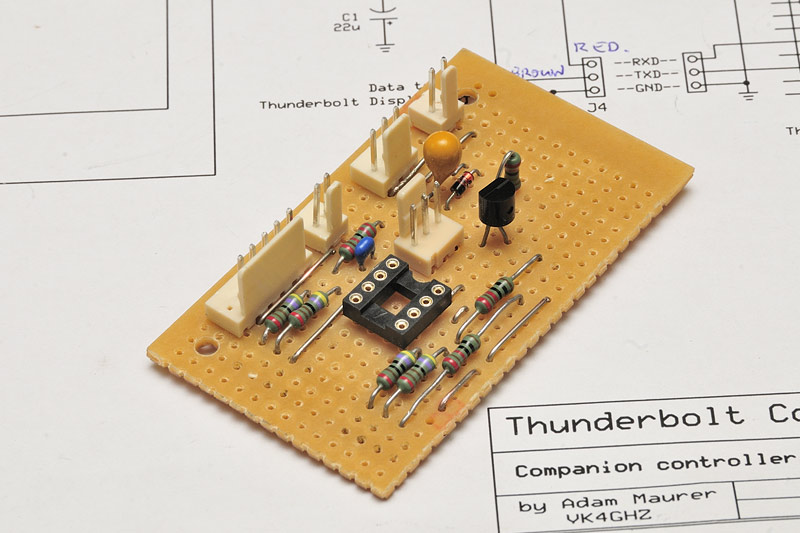
Etching a circuit board is not required, (unless you are very keen!), because the circuit is so simple, it is easy to make up on Veroboard.

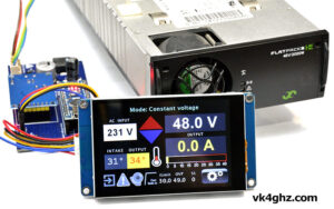
Above: ThunderBolt Commander mounted on the same bracket as a Jumbo ThunderBolt Display, inside a transverter system 4 push buttons beneath the LCD display module

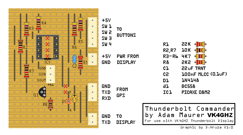
Above: Suggested Veroboard layout. “X” indicates copper trace cut underneath.
Note: link from Q1 emitter to IC1 pin 1 on copper side Note: link from IC1 pin 5 to adjacent track on copper side Note: links between header connectors. Obscured in photos, so reinforced with red line
I’m using a PICAXE 08M2, but you can use a 14M2 or the older 08M & 14M using the old style port definitions. 8M’s and 14M’s share a similar pinout on “one side”. You can use whatever you like… we only need a few input pins, and the serial out.
Running the PICAXE at 8MHz means the SEROUT is at 9600Bd.
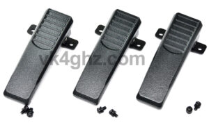
I use four buttons to send these TSIP command packets;
1) Set RX Mode to OverDet Clock
2) Set RX Mode to Full Pos 3D
3) Start Survey
4) Toggle time between UTC/GPS
It’s the first two we really want. The 4th is probably of no real value… I’m just using all 4 available I/O lines on the 08M2, for the sake of it.
Looking at the circuit, you will see how easy it is to derive a –ve rail for the RS232 zero crossing.
No need for a MAX232 chip or anything. It takes advantage of the fact that the data line from the ThunderBolt idles around –8.5V. The RS232 command packets out of this circuit swing from +5V to about –5v. RS232 specification calls for voltages greater than +3V and less than –3V, so this simple approach satisfies that, and is more than adequate.
Aside from generating the –v rail from it, the serial data “TXD” FROM the ThunderBolt loops through the Commander, to go to the ThunderBolt Display.
ThunderBolt RS-232 Data I/O
Referring to the 2-channel waveform capture below;

At top, in Yellow, is the “TXD” line FROM the ThunderBolt. This line idles at -9V. We pick this off with D1, and filter with the 10uF 25V tantalum capacitor, to generate a -9V rail.
From the left, we see the two automatic report packets that the ThunderBolt sends automatically every second. When the data is being sent, the derived –9V does have some ripple on it, as you would expect, but this is of no consequence. (See the ripple on the green trace immediately below)
The burst in green (lower trace) is a command packet (resulting from a button press) from the ThunderBolt Commander, and the yellow burst above it, not long after, is the ThunderBolt responding to that command packet. The yellow burst on the far right is the beginning of a new second, where we start to see the automatic report packets again.
PICAXE .bas File
Looking at the .bas file… you’ll see it loops around waiting for push button presses. Upon a button press, and after some software debounce, it executes the appropriate subroutine, which spits out the Trimble command packet string for whatever you are trying to do.
Cost?
If you had to buy everything, it would be about $15, but I imagine most enthusiasts will already have some of the bits… resistors, push buttons, an NPN transistor, a 1N4148 diode, caps, etc. All garden variety stuff.
In order to program the PICAXE 08M2, you will need a programing lead. The genuine AXE027 USB programming lead is recommended. In Australia, it can be obtained from [url=http://www.microzed.com.au/index.php?main_page=product_info&cPath=29&products_id=62]MicroZed Computers[/url]. Other retail outlet may also stock it, so check with your favorite supplier.
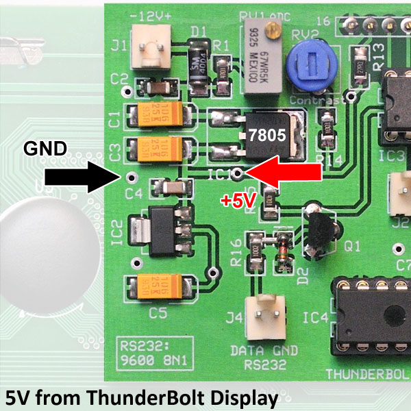
+5V Supply Rail
The +5V rail can be picked off the ThunderBolt Display, or from inside the ThunderBolt itself.
Resources:
![]() ThunderBolt Commander v1.0 PICAXE file (Original file)
ThunderBolt Commander v1.0 PICAXE file (Original file)
![]() ThunderBolt Commander v1.2 PICAXE file (Use this with v2.2 Display firmware which fixes the date error)
ThunderBolt Commander v1.2 PICAXE file (Use this with v2.2 Display firmware which fixes the date error)
![]() ThunderBolt Commander schematic (as pdf)
ThunderBolt Commander schematic (as pdf)
Now, once you have configured your ThunderBolt, you shouldn’t need to connect it to a PC/laptop again.
I recommend you connect your ThunderBolt up to a PC/laptop, and running Trimble’s tboltmopn.exe program, issue a factory reset command.

This will get your ThunderBolt back to a known start point.
From Cape Coral, Florida (USA), Denis Hruza (not yet licensed), sends in this suggested Verobord layout. Nicely done, Denis. 😀
Similar to above, but Denis spaces things out a little more, so those under-side links are now on the top side of the board. A 5-pin header is depicted for the switch, but Jaycar (here in Australia) do not stock a 5-way, which is why you see a 6-way in the image above.
Denis writes;
I made a few changes to the original layout.
– Added 2 rows to the board – Removed solder side jumper for R4 by moving R4 over and using it’s old location for a small jumper top side. – Removed solder side jumper for IC1-PIN1 to Q1 Emitter. By adding a row, I moved the jumper up top and also moved the cut lines over near D1. – Removed solder side jumpers for both +5 and GND near headers. By adding a row, I then had space for the 2 jumpers on top side.
🙂
ThunderBolt Commander by VK2GOM
Post by VK2GOM » 30 Dec 2011, 13:26
I am very happy with my finished unit.
There was one ‘burp’ on first connection to the Thunderbolt that required a Thunderbolt reset, but it has done many 3D surveys since without a glitch.
Note that this event was not the fault of the Display/Commander – it was an issue with my Thunderbolt.
Looking forward to using it in the forthcoming field days.
73 – Rob VK2GOM / G0MOH
ThunderBolt Commander by VK3YFL
Post by VK3YFL » 07 Jan 2012, 15:12
Finished building Adam’s ThunderBolt Commander yesterday and mounted in the enclosure I had already integrated the ThunderBolt and ThunderBolt Display in.
The four Commander buttons are mounted above the ThunderBolt inputs/outputs on the rear of the enclosure.
However there appeared to be an intermittent in the operation as a whole. I believe I’ve now solved that problem by replacing the 100nF greencap I had in the junk box and used as the bypass with a monolithic version which is obviously more suited to the job.
This is my first PICAXE project having last played with microprocessors many years ago back and found the whole programming process very simple, thanks to Adam’s source code.
Having the Commander integrated with the ThunderBolt and Display, eliminating the need to have a PC connected is certainly great and an ideal solution for portable use. I use the ThunderBolt on my 10GHz Field Day gear and I was never sure if it was working correctly, but now I will. It also means I don’t need to take my desk clock on the Field Day as UTC is being displayed right there in front of you.
Thanks Adam and I’d encourage others to give it a go.
Bryon
VK3YFL
ThunderBolt Commander by VK3QI
Post by VK3QI » 08 Jan 2012, 07:40
Hi Bryon,
Likewise I have successfully fitted the display unit to the front panel of the control unit for 1.2,2.4,3.4,5.7 and 10Ghz thus eliminating three things:
(1) no need to have a serial connection to the laptop
(2) no need for a UTC clock
(3) no need to remember my grid square – it is on the screen
A great project Adam, well worth the time spent using the nibbling tool to cut out the hole in the existing front panel without disassembling everything
Hope to work you on 10GHz again next weekend Bryon, Thunderbolt Commander to Thunderbolt Commander, so to speak!
Cheers
Peter VK3QI (VK3ER/p)