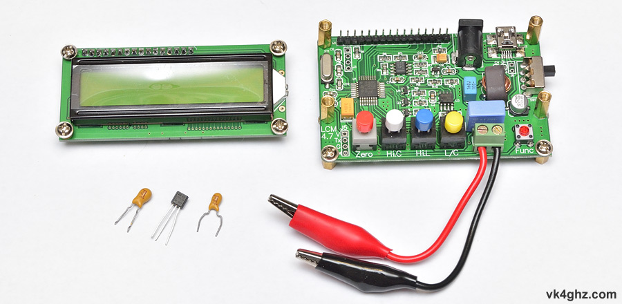
Apart from measuring regular capacitor and inductor parts, an LC100-A LC meter can be handy tool for measuring the inductance of your mini-quad motor windings, to determine if a particular motor has shorted turns or not.
To make the LC100 a bit more work bench friendly, a few modifications have been implemented.
7 – 15VDC Input Modification
The LC100-A expects a 5V power supply, either by the USB connector or the coaxial DC socket.
With the DC input socket, there is a risk of accidentally hooking up a supply of more than 5 volts, so a 5V regulator is being fitted, so that it can be powered off anything from 7 volts to the upper limit of the regulator (usually 35 volts).
The USB input remains fully functional.
Unscrew the LCD display, and pull off:

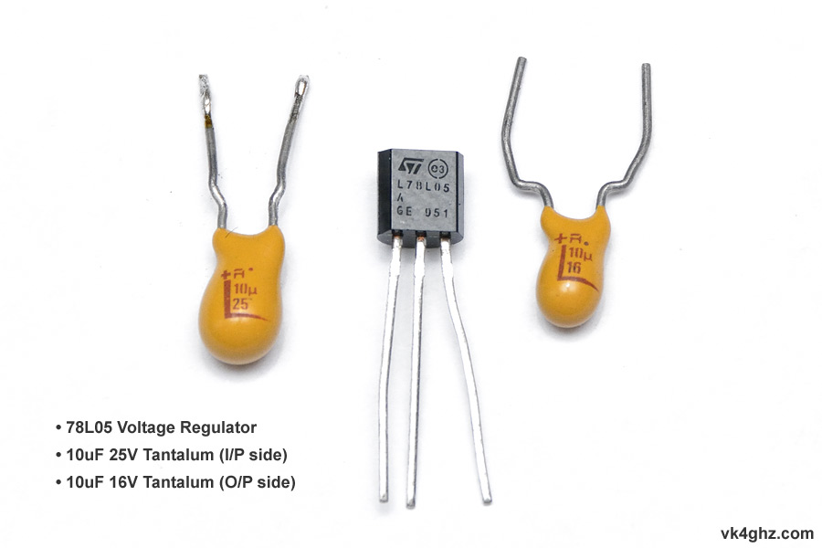
Only three components are required to make a classic 78xx regulator circuit:
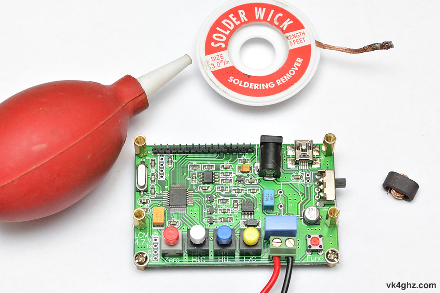
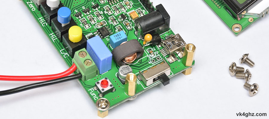
To make the board easier to work on, we temporarily de-solder the inductor L1:
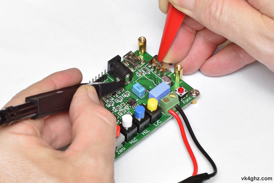
Cut the +5V PCB trace from the DCinput socket, and on the other side of the break, scrape away some solder mask so that it can be soldered to:
Check continuity to ensure you have actually cut the track:
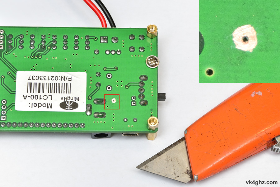
On the solder-side of the board, scrape away some solder mask around this via:
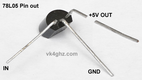
Pre-form the 78L05 regulator like so:
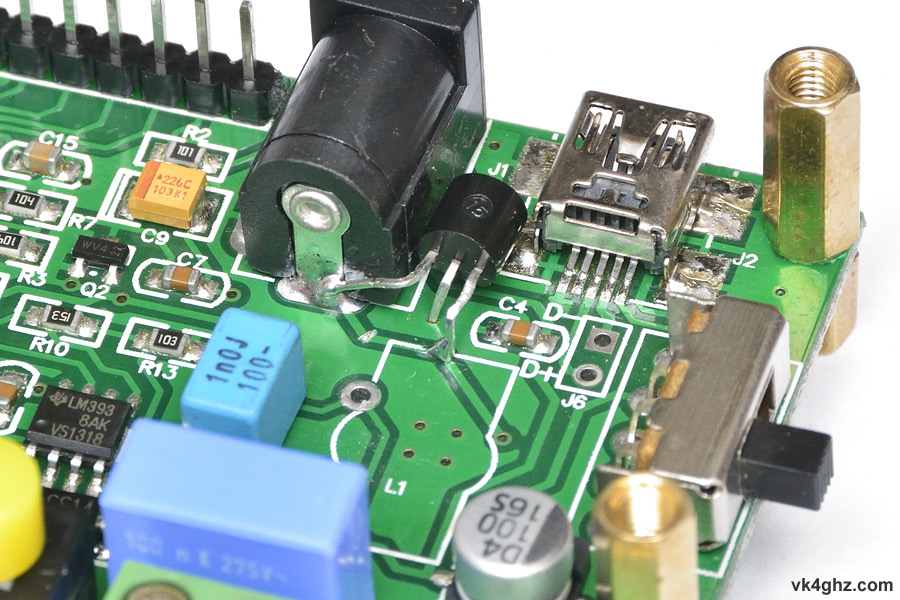
The 78L05 fits like this, noting that
• input pin soldered to DC socket
• middle pin (GND) passes through via
• output pin soldered to newly created ‘pad’
10uF 25V tantalum is soldered to the solder-side of the board – note polarity.
This is effectively across the input of the 78L05:
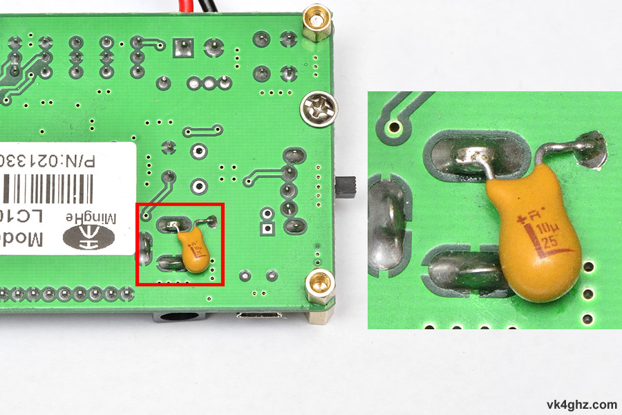
The height of the tantalum fits comfortably within height of the legs:

10uF 16V tantalum capacitor fits across the 78L05 GND and output pins – note polarity:
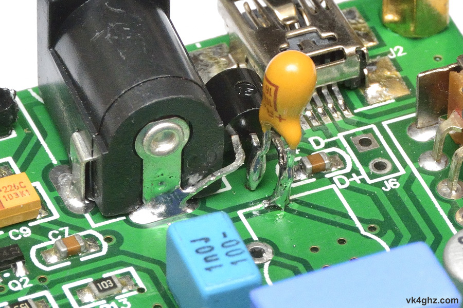
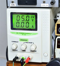
To check the regulator, set your PSU to 5V only.
With the LC100-A’s power switch in the off position (towards you), connect the PSU up to the DC socket.
Measure the output of the 78L05.
Negative multimeter lead to the side pin of the DC socket.
Postive multimeter lead to middle switch pin.
Depending on the regulator’s ‘drop out’ it should be around 3V – 4V.
If it’s 5V, there’s a problem you need to investigate!
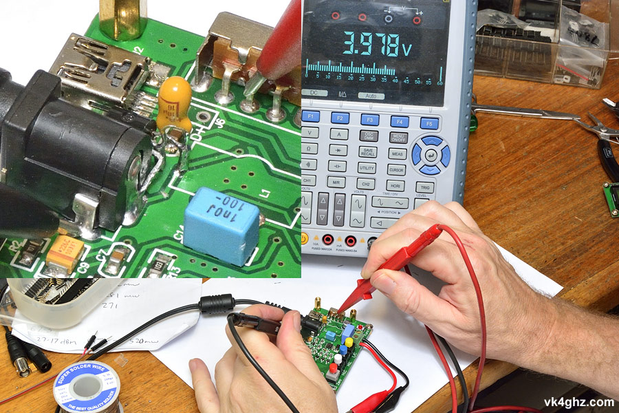
If all ok, slowly wind the PSU volts up, and you should happily see the +5V rail when the PSU is > 6.5V or so.
Refit the inductor L1, refit the LCD, and check LC100-A for normal operation:
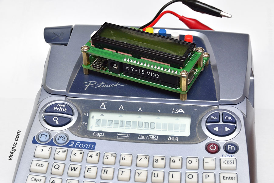
Power Input Label
As a reminder of the internal 5V regulator modification, a label has been fitted:
LCD Contrast Modification
You don’t really need to do this, but all LCDs should have a contrast control.
The LCD used in the LC100-A is a bog standard Hitachi HD44780 type module, so the contrast pin is pin 3.
Pin 3 goes to a fixed value SMD resistor, R1, so the contrast is fixed.
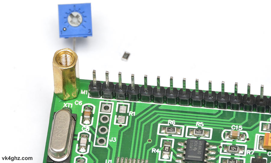
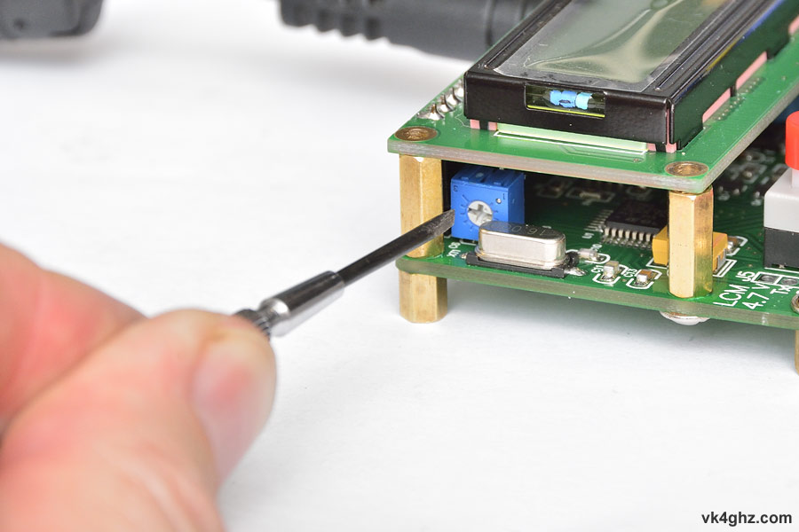
R1 is removed, and a small 10K trimpot is fitted into the vacant J3 holes like so:
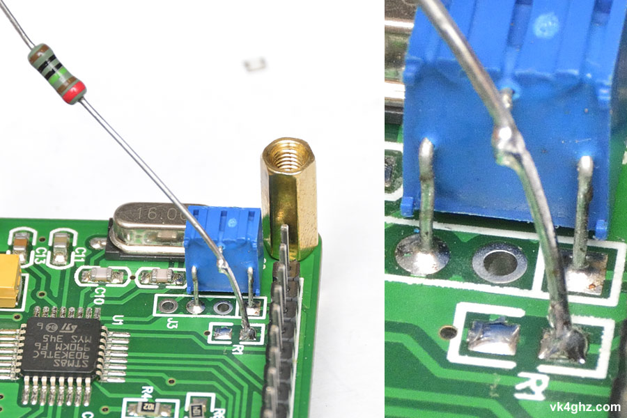
Center pin of the trimpot is extended to the R1 pad nearest the LCD header using a components leg.
LCD’s contrast can now be easily adjusted to suit the viewing angle:
Acrylic Base and Rubber Feet
The meters finish is a bit agricultural, and the M3 spacers used as feet can scratch your desk.
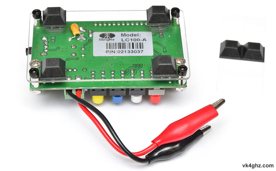
A piece of 1.5mm clear acrylic was cut out and drilled to suit, which allows you to fit some stick-on rubber feet to the base:
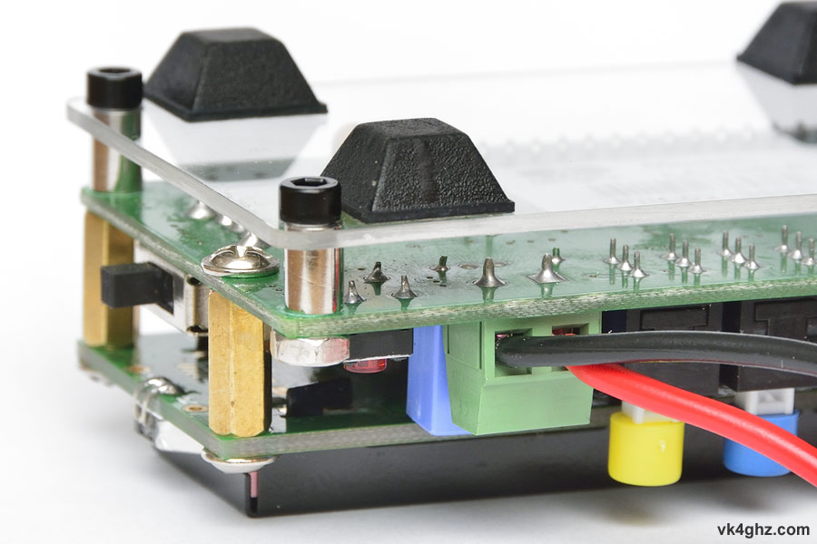
Tapped M3 spacers are replaced with 6mm non-tapped spacers, and 12mm hex-head bolts (and 2 nuts) are used:
🙂
