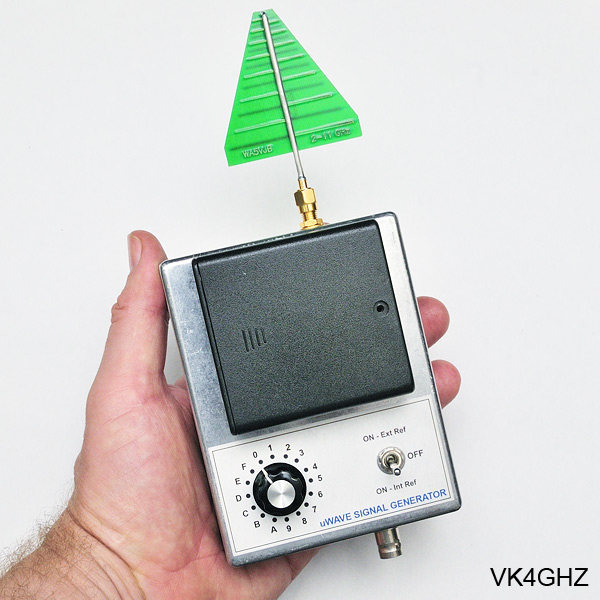
This is a small and convenient microwave signal generator, for use in the shack or out in the field as a check source.
It is based upon the popular VK3XDK PLL Synthesizer board.
The antenna is a WA5VJB log periodic, as described here.
Main design goals included;
- Hand held and light weight
- Rechargeable AA cells, offering many hours of operation
- 16 preset frequencies
- Reasonable frequency stability with internal 10 MHz reference
- External 10MHz reference input


The original idea was to use an ISOTEMP 134-10 Oven Controlled Oscillator (OCXO) as the 10 MHz reference, but the 134-10’s heavy current requirements ruled this out.
(Barely 40 minutes was obtained using 8 x AA 1.6V Nickel Zinc cells)
I then discovered RS had a range of low cost Temperature Controlled Crystal Oscillators (TCXO), and chose the Mercury VM53S.
You can download the VM53S datasheet from that RS page.
When ordered online, RS offers free delivery with this part.
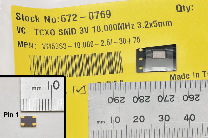
Above: Mercury VM53S 10.000 MHz reference, +/- 2.5ppm. Small, but can be soldered to PCB with a standard Weller tip
Have a closer look at the specifications of these devices. They make a standard crystal look totally prehistoric!
The manufacturer states;
By the integration of a resistor / capacitor compensation network and a sensor circuitry, the frequency
stability of a crystal oscillator (XO) can be improved by about 100 times.
They run off 3.3V, which conveniently, is the supply rail found on a VK3XDK PLL Board.
Pin 1, voltage control, is used to tweak the operating frequency.
At $15.40 (inc) they are a low cost, and very practical solution, when GPS lock is not required. 😀
(An external reference input does allow for a GPS-locked reference, if ever required.)
Another interesting part from RS, is a 16-position, HEX encoded rotary switch.
This provides an external switch that is a direct replacement for the on-board DIP switch, making it easy to access all 16 preset frequencies. (Also free delivery, when ordered online)
The “RF1” output SMA PCB launcher (f) jack was replaced with a longer version.
All other parts are bog standard. Diecast box, 15mm M3 spacers, M3 screws, centre-off DPDT toggle switch, BNC jack, 4 x AA battery holder, 2K multi-turn trimpot, 470pF ceramic capacitor.
We could mount the VM53S TCXO “dead-bug” style, but with one small modification, the existing PCB copper area can accommodate the VM53S, and it firmly fixes it to the PCB.
The following images should be self explanatory.
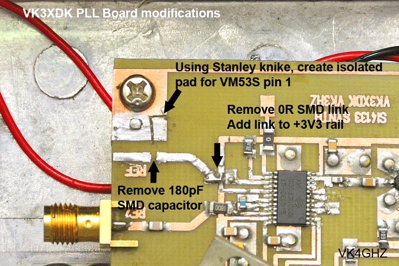
Using a sharp Stanley knife etc, create an isolated pad for TCXO pin 1.
Remove the 180pF capacitor (we will use an external ceramic cap, mounted on the toggle switch)
Remove the 0R SMD link.
Fit a new link from the +3V3 rail to the track that now feeds pin 4 of the TCXO.
This leaves the pad going to pin 15 of the Si4133 (10 MHz reference in) a spot where we can solder a wire link to the toggle switch.
Note:
This is one of Graham’s prototype PLL boards, and it does not have the same production finish (plated through-vias), as the commercially manufactured PCBs.
It looks different, but is essentially the same as your PLL board though.
However, it does have an Si4133D fitted – not a “G”, enabling more versatile frequency selection.
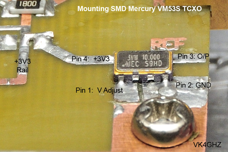
Above: Small and a bit fiddly, but you can solder the VM53S to the PCB using a standard Weller tip.

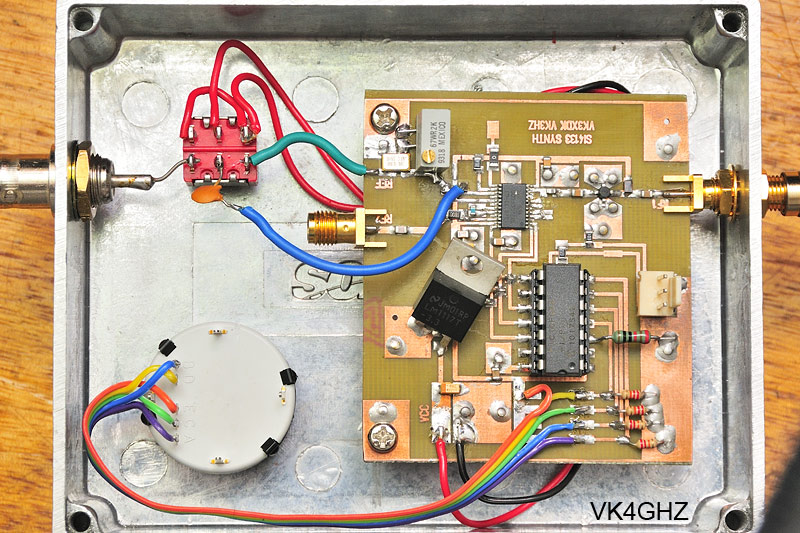
Above: Toggle switch wiring. One side switches battery volts, the other side switches 10 MHz feeds.
16-position HEX encoded rotary switch ideal DIP switch replacement
“RF1” SMA output jack (PCB launcher type) is replaced with a longer version.
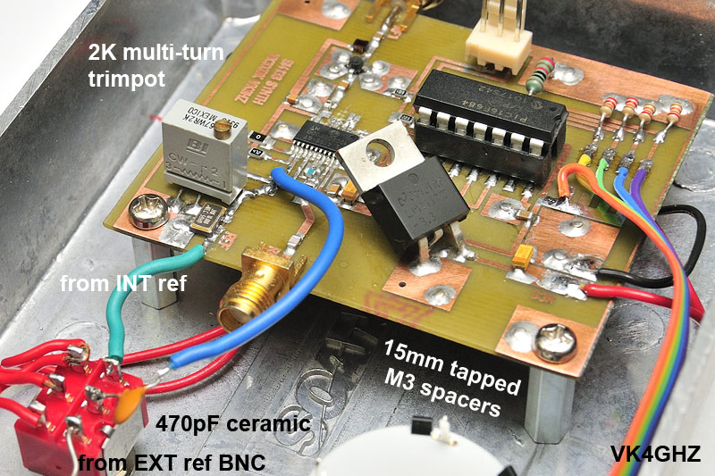
2K trimpot to tweak master 10 MHz reference.
One side to GND, the other side to +3.3V, wiper to pin 1.
The SMD coupling capacitor that was removed measured 180pF.
The Si4133 datasheet specifies a 560pF capacitor, but that is not a critical value.
I fitted a common 470pF from the parts bin.
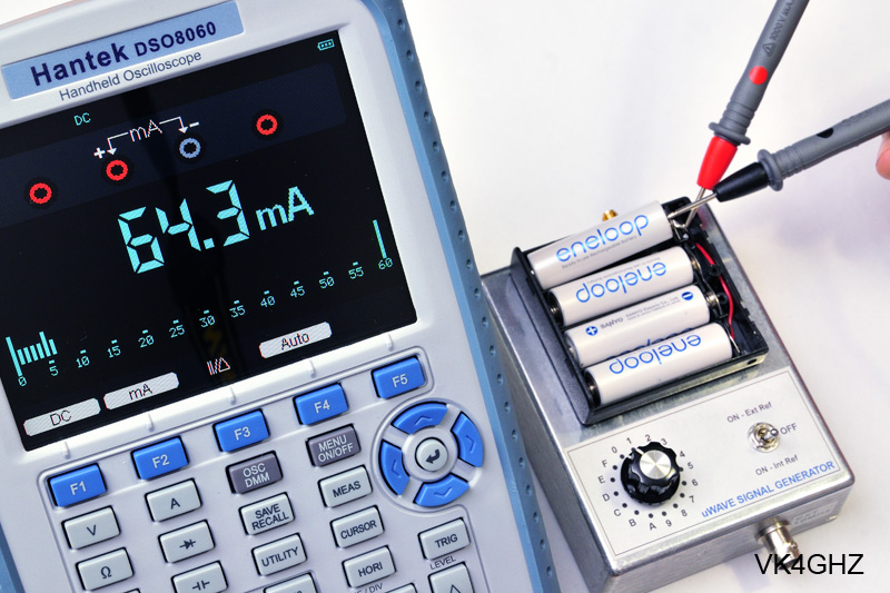
Above: Draws less than 65mA, and will run for many many hours using standard 1.2V rechargable cells
AA cells are easy to access and change.
I dislike having to unscrew an enclosure apart to access internal batteries, and more often than not, cells are forgotten about, which eventually results in corrosion problems.
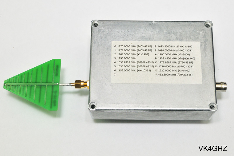
Above: Frequency look-up chart label on under-side
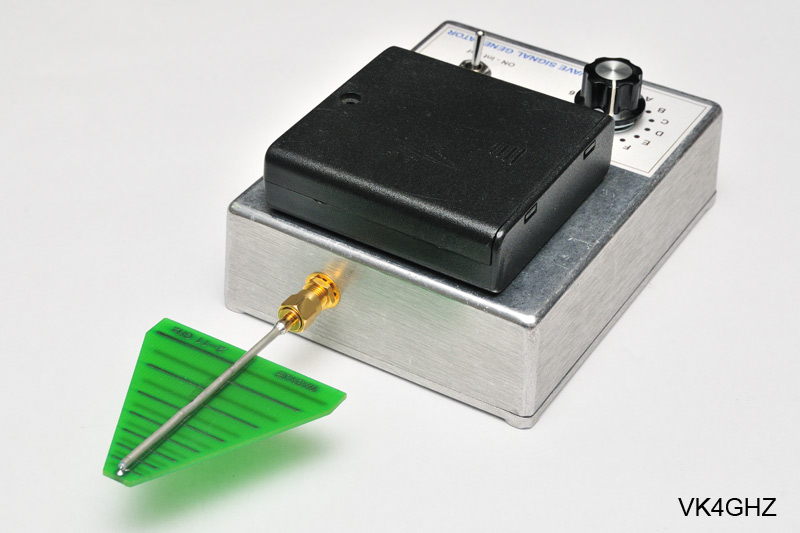
Above: Business end with a WA5VJB log periodic as antenna

Above: Output at 1970 MHz. Note frequency, to 10Hz! (Spectrum analyzer uses a GPS-locked reference)
For higher output level, useful for harmonics up to 10 GHz, the ERA2 MMIC and 27nH inductor is fitted (which Graham, VK3XDK, thoughtfully supplies with the PLL board).
Further enhancements could include bringing the PLL board’s “IF” synthesizer output to an SMA jack, if required.
This is a low cost signal generator, that can be used in the field as a check source, whose frequency can be set accurately and offers very good stability.
😀