Here’s an interesting rainy day project for microwave enthusiasts to experiment with.
And as luck would have it, it poured down today!
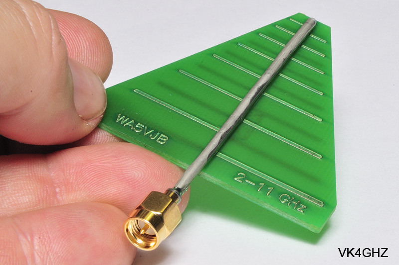
From Kent Electronics it’s a PCB based 2 -11 GHz log periodic antenna.
Kent Electronics describe this as;
This log periodic printed circuit board antenna gives great performance from 2100 – 11000 MHz.
This range includes wireless networking at 2.4GHz (802.11b/g) and 5.8GHz (802.11a).
This wide range works well for frequency sweeps and other broadband applications.
This can also be easily applied to other hobbyist applications in this range.
It’s a great quality double-sided PCB with silkscreen, and costs all of USD$6.00!
Add USD$2 for international first class mail, and it should arrive a week or so later.
We don’t attach connectors/coax unless requested since many people often have different needs, especially if it comes to manufacturer unique/specific connectors.
And even then it is an added charge.
So the burning question, how much power can you feed into something like this?
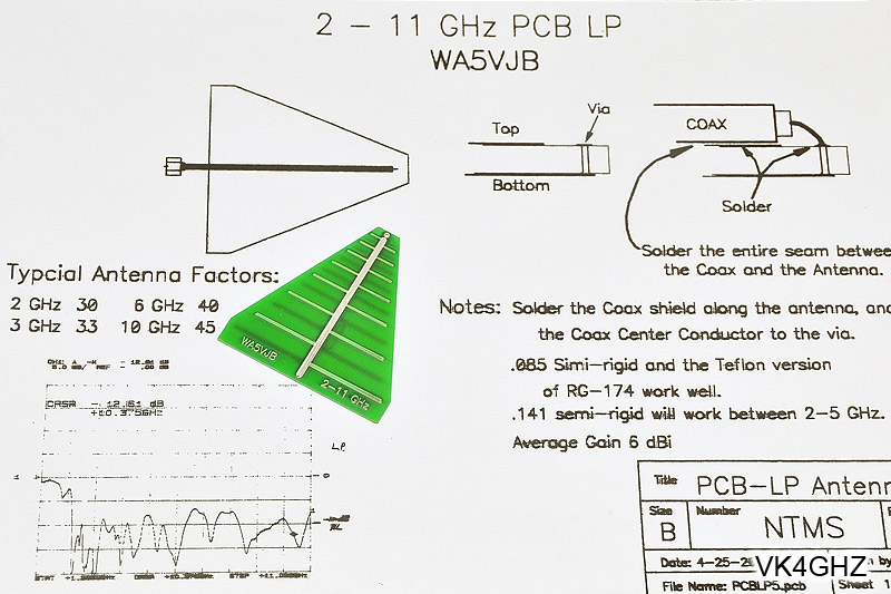
Kent offers some insight with an interesting document
![]()
Designing PCB Log Periodic Antennas (pdf 17kb).
Kent also wrote
I wish I could test one of these antennas to destruction, but I just do not have enough power.
At 400 MHz, the antenna has a relatively large active area and can easily take 100 watts.
As you go up in frequency, the active area gets smaller and smaller, and the dielectric loss goes up.
At 3.4 GHz one has been burned up with 40 watts of FM.
At 10 GHz a 10 watt prolonged carrier smoked another 2-11 GHz LP.
I am expecting some feedback on their power handling from local EME’ers.
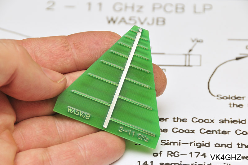
Above: PCB is 54mm long, and 53mm wide at the reflector end
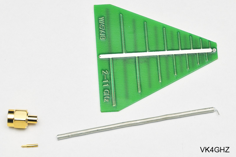
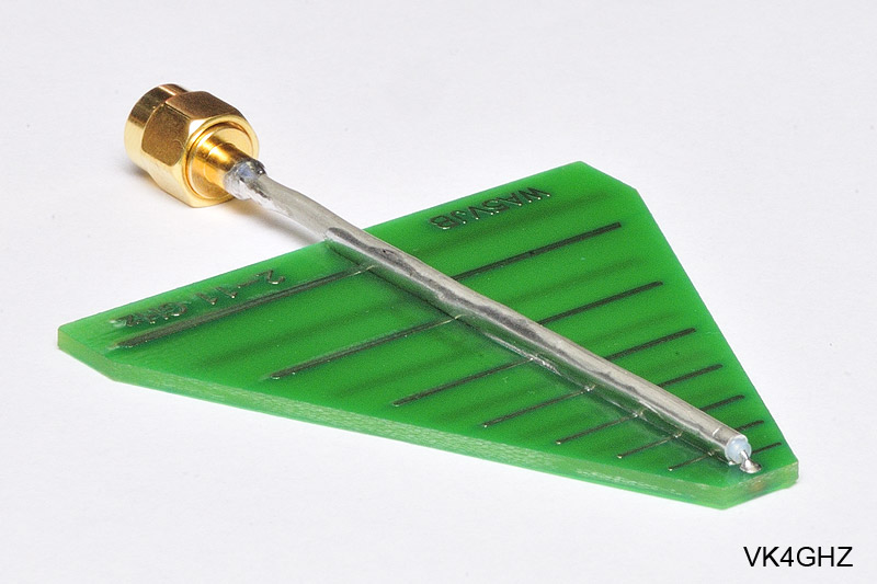
Above: Some 085 hardline from the junk box, and an SMA (m) connector to suit
I’ve always had an interest in microwaves, but it was never pursued in the past, because of the perceived difficulty with the “plumbing”.
However, nothing can be further from the truth.
Hardline is soooo easy to work with. In fact it’s very hard to bugger up!
The inner dielectric is teflon, so it’s easy to solder, without the worry of melting anything!
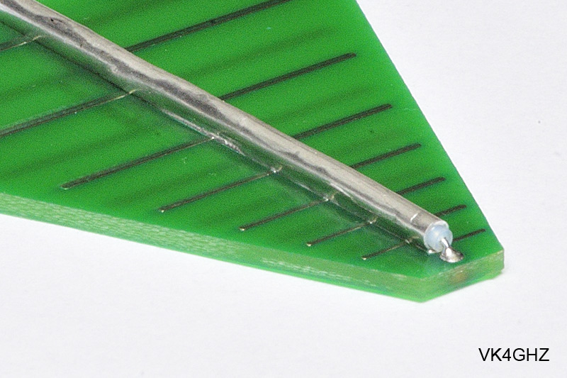
One end of the 085 is prepared, and soldered into the PCB via at the log’s director end.
A seam of solder runs along the hardline, fastening it to the log periodics “boom”.
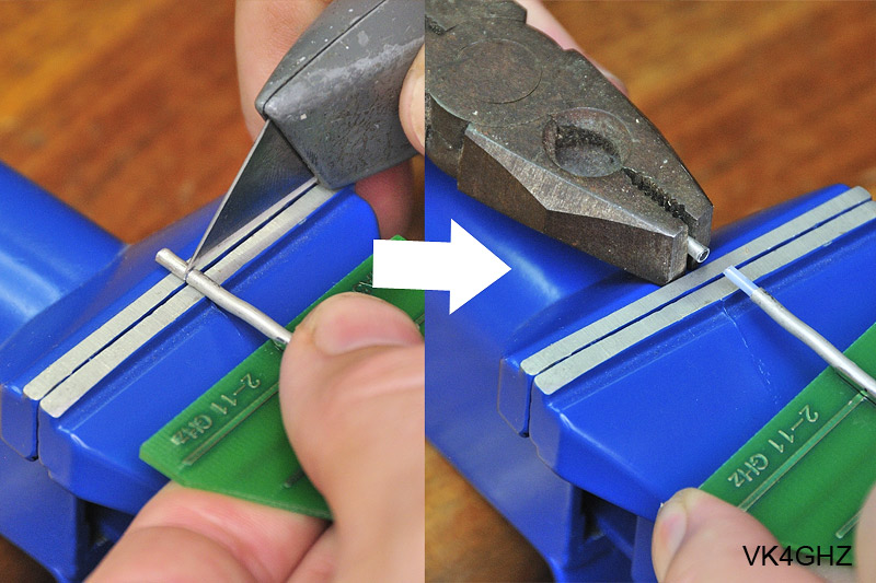
Above: Score around the outer outer jacket, and twist off with pliers.
Then trim the inner dielectric away, and tin the inner conductor, and fit the centre pin, as you would with regular coax.
Slide on the SMA connector body.
Again dead easy to work with, and run a bead of solder around the body, where it meets the outer jacket.
The finished log periodic antenna…

The main application here is to use it as the antenna for a portable GHz signal generator, for use in the field, as described here.
(A VK3XDK Synthesizer, with the ERA2 MMIC fitted for stronger harmonics, + 10MHz reference, in a box!)
Something that can be planted as a signal source a few hundred metres away, and used to help setup a dish feed.
The log periodic will also be interesting to play around with as a dish feed itself.
😀