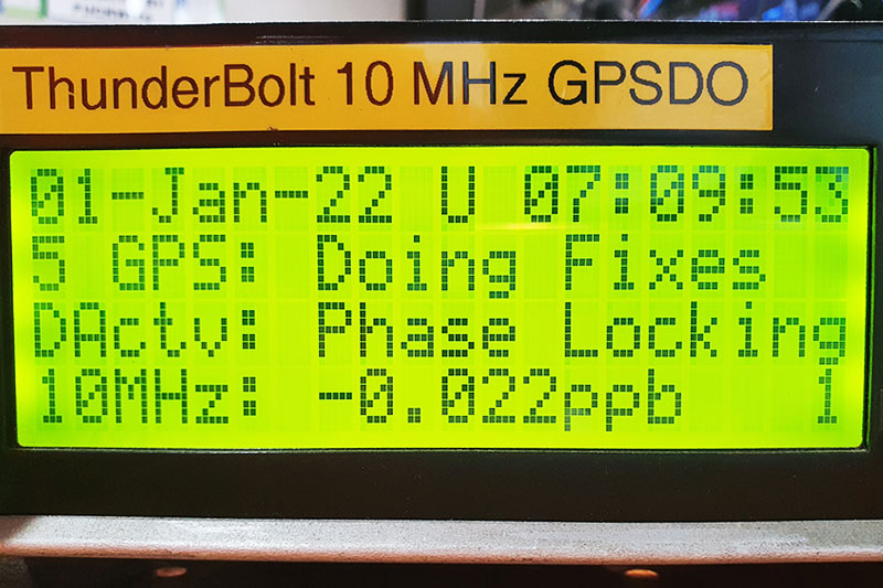
This v2.4 firmware update deletes support for years 2020 and 2021 (obviously no longer required!), which now creates space in the PICAXE28X2’s limited memory for date support to end of 2035.
Background:
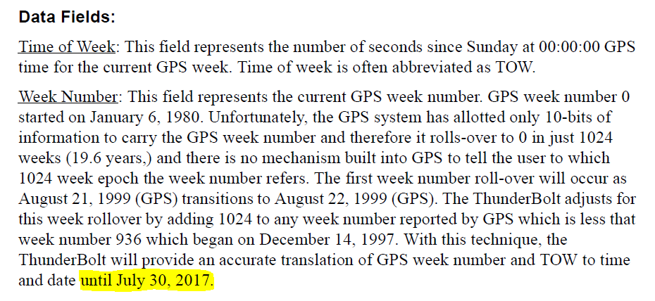
Thunderbolt does not translate date fields correctly since the roll over from July 29 to 00:00:00 July 30, 2017.
From Trimble:
Since then my PICAXE firmware has reconstructed the date itself by using GPS Week number and Time of Week fields and doing a bit of math.
Thunderbolt display micro-controller
The microcontroller on the Display board is a PICAXE 28X2, this is the chip in the 28-pin IC socket.
The other chip soldered to the PCB is a math co-processor – and does not need to be touched.
You will need the following
• PICAXE AXE027 USB programming lead (or direct equivalent)
• PICAXE Editor program http://www.picaxe.com/Software/PICAXE/PICAXE-Editor-6/
• You may need a breadboard, 22k resistor, 10k resistor, and 5V supply to make a temporary PICAXE programming jig
Understand that I cannot answer random questions about other programming leads – use a proper AXE027 if in doubt.
For answers about using the PICAXE Editor – refer to the PICAXE website for FAQs etc
Re-programming the Display micro-controller
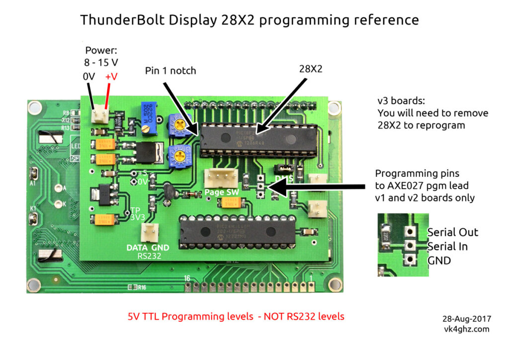
If you have a v1 (2011) or v2 (2012) display board, you have two options to program the 28X2;
1) on-board, there are programming pads you can temporarily solder to.
2) off-board, in a breadboard etc
v3 (2013) boards do not have these programming pads, so you will need to remove the 28X2 and program it off-board.
Assess whether you should remove your Display board from its enclosure to properly access the programming pads or removing the PICAXE without the risk of bending or causing fatigue to the pins.
Programming on-board
• display board needs to be powered up whilst programming.
• connect up PICAXE programming lead (AXE027) or equivalent
• using PICAXE Editor, program slot 0 and slot 1 (order is not important)
• remove programming lead
Programming off-board
• disconnect power to Thunderbolt
• NOTE ORIENTATION of the PICAXE 28X2
• carefully remove 28X2
• insert 28X2 into your breadboard programming jig
• connect up PICAXE programming lead (AXE027) or equivalent
• using PICAXE Editor, program slot 0 and slot 1 (order is not important)
• re-insert the 28X2 into your Display board, noting orientation
To display the Thunderbolt’s internal firmware version, the Thunderbolt, Commander and Display need to power up together.
V1 and V2 programming interface:
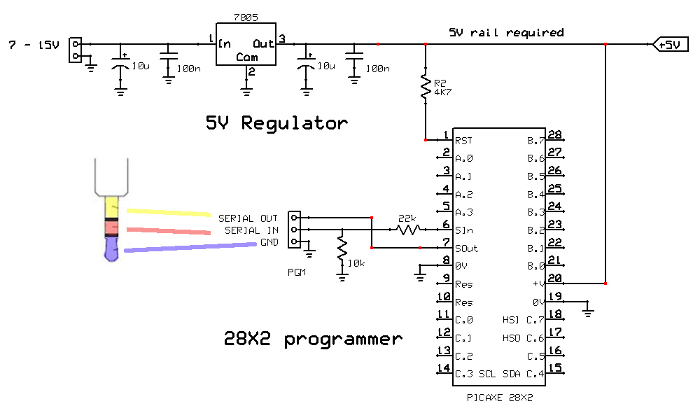
V3 – suggested circuit for off-board programming:
If you cannot set a PSU to 5.0V, use a standard 7805 type regulator circuit to generate a 5V rail
10k and 22k programming interface resistors must be used.
A small breadboard is ideal for knocking up this circuit on.
PICAXE .bas File Downloads:
Notes:
If you haven’t previously update to v2.0 or above you will need to update ALL Slots.
If you have previously updated to v2.3, only Slots #0 & #1 need updating.
Do not be concerned with the slot number or the programming order, as it’s hard-coded into the code – just program the files as-is.
Current Versions:
Slot 0 v2.4
Slot 1 v2.4
Slot 2 v2.2
Slot 3 v2.3
Video
Adam provides some background and gives an overview of the update.
