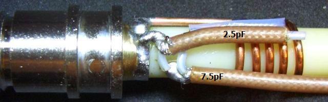
Fixing a Diamond X-500 2/70 antenna
Fixing a Diamond X-500 2/70 antenna
Adam, Brisbane
vk4ghz.com
VK4GHZ on Youtube
VK4GHZ on Odysee
10 things that happen when you stop checking Facebook constantly: http://tiny.cc/t5h7cz
How to quit Facebook: https://www.consumerreports.org/social- ... -facebook/
vk4ghz.com
VK4GHZ on Youtube
VK4GHZ on Odysee
10 things that happen when you stop checking Facebook constantly: http://tiny.cc/t5h7cz
How to quit Facebook: https://www.consumerreports.org/social- ... -facebook/
-
VK3BJM
Re: Fixing a Diamond X-500 2/70 antenna
Aah - Automotive Bog; is there anything it can't do?  (Apologies to Matt Groening & co...)
It's a special feeling, that sinking realisation that "I might just have completely stuffed this up with one moment's miscalculation/inattention..."
Nice recovery!!
73,
Barry
VK3BJM
It's a special feeling, that sinking realisation that "I might just have completely stuffed this up with one moment's miscalculation/inattention..."
Nice recovery!!
73,
Barry
VK3BJM

Re: Fixing a Diamond X-500 2/70 antenna
Well done Adam,
How did you fit the brass base back into the aluminum tube?
How did you fit the brass base back into the aluminum tube?
Lou - VK3ALB
Being right doesn't excuse bad behaviour
Being right doesn't excuse bad behaviour
Re: Fixing a Diamond X-500 2/70 antenna
Hi Adam,
Good job but what was actually wrong? Possibly the aluminium to brass at the thread maybe?
cheers,Frank
Good job but what was actually wrong? Possibly the aluminium to brass at the thread maybe?
cheers,Frank
Re: Fixing a Diamond X-500 2/70 antenna
Lou, I simply screwed it back on!VK3ALB wrote:How did you fit the brass base back into the aluminum tube?
There are a few turns of thread left.
In hindsight, instead of cutting a 6mm strip off the end of the tube, 3 or 4mm might have been enough to "crack the thread".
The only purpose of this thread is to hold the N-connector in place, and to withstand any downward thrust from the feedline.
With a smaller amount of thread, I will have to ensure the feedline has adequate strain relief to the mast, so the N-conn isn't pulled out from the bottom of the X-500 itself.
Adam, Brisbane
vk4ghz.com
VK4GHZ on Youtube
VK4GHZ on Odysee
10 things that happen when you stop checking Facebook constantly: http://tiny.cc/t5h7cz
How to quit Facebook: https://www.consumerreports.org/social- ... -facebook/
vk4ghz.com
VK4GHZ on Youtube
VK4GHZ on Odysee
10 things that happen when you stop checking Facebook constantly: http://tiny.cc/t5h7cz
How to quit Facebook: https://www.consumerreports.org/social- ... -facebook/
Re: Fixing a Diamond X-500 2/70 antenna
Frank, I don't know, but the SWR went noticeably high one day.VK7DX wrote:Good job but what was actually wrong? Possibly the aluminium to brass at the thread maybe?
My initial thought was a capacitor had gone open circuit.
In reality, performance was probably diminishing slowly over time, as moisture entered, and the internal foam spacers deteriorated, etc.
I did try to Google this topic, to see if anyone had posted pictures before, but I couldn't find any.
Just needed a damn good clean of all the joints.
Adam, Brisbane
vk4ghz.com
VK4GHZ on Youtube
VK4GHZ on Odysee
10 things that happen when you stop checking Facebook constantly: http://tiny.cc/t5h7cz
How to quit Facebook: https://www.consumerreports.org/social- ... -facebook/
vk4ghz.com
VK4GHZ on Youtube
VK4GHZ on Odysee
10 things that happen when you stop checking Facebook constantly: http://tiny.cc/t5h7cz
How to quit Facebook: https://www.consumerreports.org/social- ... -facebook/
-
VK2TDN
Re: Fixing a Diamond X-500 2/70 antenna
well done Adam,
I have done the occassional restoration on my X200 a couple of times .... the last time that the SWR went throught the roof, I pulled the antenna down and found many fine cracks in the fibreglass cover right up near the top of the antenna.
Years of being in the wonderful Australian sun
what prob happened with yours as with mine moisture had ingressed somewhere, mine was still very wet inside, the whole length of the antenna, but in the 6 months that yours had been lying around it had dried out.
Overall they are a great antenna
Dave
VK2TDN
-
VK7HDX
Re: Fixing a Diamond X-500 2/70 antenna
Hi Adam,
I have a baby X-50 which only 7 years old and is great for opening DX repeaters. But if anything goes wrong (fingers crossed) I will have a reference point now. By the way great pictures too.
73..Karl
VK7HDX
I have a baby X-50 which only 7 years old and is great for opening DX repeaters. But if anything goes wrong (fingers crossed) I will have a reference point now. By the way great pictures too.
73..Karl
VK7HDX
-
PE2WDO
Re: Fixing a Diamond X-500 2/70 antenna
Hi,
actually Dutch ham PA0FRI has 'pimped' his X510 to handle 200W+ by replacing the 500V capacitors at the base
by little pieces of teflon coax.
More information on the X510 construction can be found on his website: http://WWW.PA0FRI.COM (X510 page is also available in English)
73
Willem
PE2WDO
actually Dutch ham PA0FRI has 'pimped' his X510 to handle 200W+ by replacing the 500V capacitors at the base
by little pieces of teflon coax.
More information on the X510 construction can be found on his website: http://WWW.PA0FRI.COM (X510 page is also available in English)
73
Willem
PE2WDO
-
VK2KRR
Re: Fixing a Diamond X-500 2/70 antenna
Ive actually got a VERY long Diamond vertical mono band 2m vertical. Off hand im not sure what its called or the length but I could dig it out of the shed and find out. Its got an issue with burnt out capacitors or something of that nature in the base section. Perhaps I could look at fixing that one up to after looking at Adams posting here.
-
VK2XSO
Re: Fixing a Diamond X-500 2/70 antenna
Ah ! Excellent. Thanks for the post.
My Diamond is also about 20 years old and I suspect that it will be suffering the same problems.
The SWR had been getting slowly and noticeably worse over the past year. I had swept it from 30MHz to 500MHz and noticed that the antenna's
performance is now better out of band. The antenna is down off the tower and I was contemplating taking it apart in the next few weeks.
I think that will make the task almost trivial. Thank you
-
VK2TDN
Re: Fixing a Diamond X-500 2/70 antenna
staying on the theme of repairing Diamond X -series antennas
I have been making repairs on a brand new Diamond X-7000 2m, 70cm, 23cm co-linear. Fred, (name changed to protect the guilty) (NOT ME) rushed into service his new antenna and jammed the sharpened solid centre core of some RG213(Benelec style) into the female centre pin of the N connector on the base of the antenna.
This, as you could imagine, damaged the splines of the centre pin.
He managed to unsolder and pull off the outer casing of the N connector from the antenna base, but was unable to effect repairs. Somewhere along the line one of the matching disc ceramic caps in the base loading section was also damaged.
The cap is a 12pF 500V, which I was able to replace. I decided to use the female centre pin from a LMR400 N connector but still had to file down the brass rod coming down from the loading section to fit into the N conn. pin.
Whilst I had the antenna apart I noticed some of the solder joints on the phasing sections were a bit "dry joined" looking so removed the old solder and resoldered, producing a nice shiney joint.
I also resoldered the full circumference of the brass to brass parts at the lower end of the base loading section (see the right side of pic 1)
below several pic of the work done...
cheers
Dave
VK2TDN
I have been making repairs on a brand new Diamond X-7000 2m, 70cm, 23cm co-linear. Fred, (name changed to protect the guilty) (NOT ME) rushed into service his new antenna and jammed the sharpened solid centre core of some RG213(Benelec style) into the female centre pin of the N connector on the base of the antenna.
This, as you could imagine, damaged the splines of the centre pin.
He managed to unsolder and pull off the outer casing of the N connector from the antenna base, but was unable to effect repairs. Somewhere along the line one of the matching disc ceramic caps in the base loading section was also damaged.
The cap is a 12pF 500V, which I was able to replace. I decided to use the female centre pin from a LMR400 N connector but still had to file down the brass rod coming down from the loading section to fit into the N conn. pin.
Whilst I had the antenna apart I noticed some of the solder joints on the phasing sections were a bit "dry joined" looking so removed the old solder and resoldered, producing a nice shiney joint.
I also resoldered the full circumference of the brass to brass parts at the lower end of the base loading section (see the right side of pic 1)
below several pic of the work done...
- 1 ... a close up of the loading section... you can see a glimpse of the brown ceramic cap through the hole.
- 2 ... overall view of the base section
- 3 ... closeup of the filed down brass rod and the 2 female centre pins (LMR400 pin on the top)
cheers
Dave
VK2TDN
-
VK2TDN
Re: Fixing a Diamond X-500 2/70 antenna
and pic 4.....
cheers
Dave
VK2TDN
- 4 ... one of the phasing sections with the left hand joint resoldered
Dave
VK2TDN
-
VK2TDN
Re: Fixing a Diamond X-500 2/70 antenna
VK2XSO wrote:Ah ! Excellent. Thanks for the post.
My Diamond is also about 20 years old and I suspect that it will be suffering the same problems.
The SWR had been getting slowly and noticeably worse over the past year. I had swept it from 30MHz to 500MHz and noticed that the antenna's
performance is now better out of band. The antenna is down off the tower and I was contemplating taking it apart in the next few weeks.
I think that will make the task almost trivial. Thank you
I could almost garantee that its got damp inside like my X200, commented on in an earlier post
look for cracks in the fibreglass radome near the top of the antenna that will let the rain in.
I found my one totally saturated inside, all the foam spacers had to be dried out in the sun.
Dave
-
VK2TDN
Re: Fixing a Diamond X-500 2/70 antenna
they are pretty easy to replace .... well at least the dual bands ones are. this latest tri-band antenna had the base loading coils and caps enclosed in that black plastic housing, which made it a little more difficult, but not impossible with a 400deg and resonably fine tipped soldering iron.VK2KRR wrote:Ive actually got a VERY long Diamond vertical mono band 2m vertical. Off hand im not sure what its called or the length but I could dig it out of the shed and find out. Its got an issue with burnt out capacitors or something of that nature in the base section. Perhaps I could look at fixing that one up to after looking at Adams posting here.
the disc ceramic caps are rated at 500V
cheers
Dave
-
VK2TDN
Re: Fixing a Diamond X-500 2/70 antenna
I'm really hoping that the X7000 will be working again soon... as I have inherited it from "Fred" 
it has very respectable spec's
3 x 5/8 on 2m = 8.3dB (presumably i, it doesnt specify) gain
8 x 5/8 on 70cm = 11.7dB (presumably i, it doesnt specify) gain
14 x 5/8 on 23cm = 13.7dB (presumably i, it doesnt specify) gain
max power rating = 100W on 2m and 70cm; 60W on 23cm
VSWR < 1.5 across each band
VSWR plots show main minimums of 1.1:1 @ 145MHz ; 1.1:1 @ 435MHz and 1.15:1 @ 1285MHz
worst VSWR shown on the plots is on 23cm rising from 1.5:1 @ 1270MHz to 2:1 @ 1260MHz
cheers
Dave
-
VK2XSO
Re: Fixing a Diamond X-500 2/70 antenna
Thanks Dave,VK2TDN wrote: I could almost garantee that its got damp inside like my X200, commented on in an earlier post
look for cracks in the fibreglass radome near the top of the antenna that will let the rain in.
I found my one totally saturated inside, all the foam spacers had to be dried out in the sun.
It's never had water in it that I've found. And there doesn't appear to be any cracks or holes for water to get in. The joins would be mostly likely
for any water to get in with capillary action.
I've planned to stripp it down tonight.
-
VK2XSO
Re: Fixing a Diamond X-500 2/70 antenna
OK... the task has been completed.
The cause of my problems was a broken 10pf capacitor. It has a small fracture that wasn't obvious until I started cleaning some gunk from around the
bottom of the flange with a soft brush. It was a little damp inside the radome, but no water as such in there. Especially after all this rain.
I didn't have to do anything complex with the bottom support tube where the connector is. Just undo the two grub screws and it slides out, coil and all.
The first element is floating at the joiner, not fixed like Adam's. The 1.5pf shunt is 2pf in mine and it earths out on the connector side of the coil, not the antenna side.
So having repaired that I took the radome off all the sections and had a look at each.
The bottom coil had been deformed from the antenna being disassembled and reassembled a few times over the years.
I took a small piece of dowel and pushed it into the coil to straighten it and set the coil back to a more even spacing.
The elements weren't corroded very much, except where the steel crimps meet the copper/brass.
The coils had a little bit of green copper oxide on them. The wire brush took care of the delicate parts and the rotary wire brush on the drill cleaned up the coils.
The straight sections I cleaned up with some steel wool.
A couple of new pieces of heat shrink over the loading capacitors and a nice thin coating of petroleum jelly over the elements and coils and it looks good.
The sponge supports have turned to s**t. Yick ! While a couple of them were ok, most of them were just horrible goo.
I replaced them with some pieces of styrofoam cut into cylinders and they work fantastic as spacers in the radome.
I can now shake the antenna and it doesn't rattle at all.
Finally some self amalgamating tape over the joiner flanges which should help keep water out just in case.
The SWR is fine across both 2m and 70cm, but the real results will come in tomorrow when I mount it on a pole outside and sweep it.
I've got another damaged X500 sitting in the shed that I picked up at a field day for $20. I've not had any call the fix it, I was keeping it as spare parts for this antenna. But now I might as well dig it out and check it out
-
VK2TDN
Re: Fixing a Diamond X-500 2/70 antenna
awesome Ash,
a good job well done
yeah go for broke on the other one as well give it a good refurb and get it up in the air
The Diamond's really are a good reliable brand, considering the hell they get in the the
Australian extreme heat etc
Dave
a good job well done
yeah go for broke on the other one as well give it a good refurb and get it up in the air
The Diamond's really are a good reliable brand, considering the hell they get in the the
Australian extreme heat etc
Dave
-
VE2AW
Re: Fixing a Diamond X-500 2/70 antenna
Hello everyone,
This indeed was a very fine and informative posting by Adam and which will be of great use to me. I happen to own a similar antenna and mine also appears to be in the same condition that Adam's antenna was in, before he attempted to revive his.
Mine is currently stored in three parts each, for both the antenna elements and for the radome.
Problem now is that I don't know which of the elements is the center and which is the upper element...
Would anyone, by any chance have either a schematic diagram or possibly a picture of the layout of the elements? I have been looking for the information for approximatly two years and today is my lucky day as I came upon your Discussion Forum.
Many thanks for your time and 73.
Gerry VE2AW
McMasterville, Quebec
FN35JM