A Trimble ThunderBolt GPS Disciplined Oscillator (GPSDO) is the main 10 MHz station reference, and was originally built into a dual-band 2.4/3.4 GHz transverter system.
Now that a larger and more powerful 3.4 GHz PA module is to be installed in this system, the ThunderBolt must be re-located out into it’s own box.
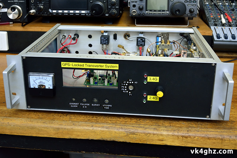
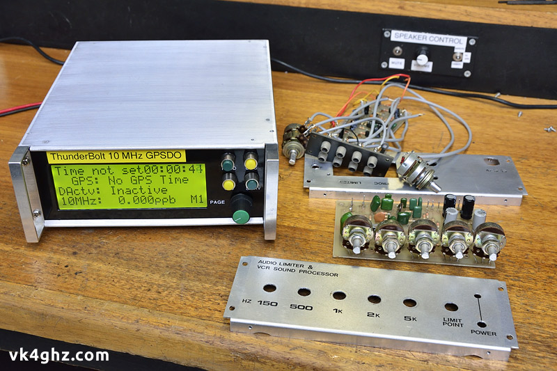
Whilst the ThunderBolt was internal, removing the associated Thunderbolt Display, (along with it’s page switch, and the four push buttons for the ThunderBolt Commander), really does leave a big hole in the front panel.
What case could be used to house a ThunderBolt?
With society dumbing down, and the decline in homebrewing of electronics projects, suitable project enclosures have either become very expensive, or difficult to obtain. Or both.
A quick rummage around, and an obsolete project (from the late 80’s or early 90’s) was found.
Lucky, because it was sitting on the “to be thrown out” shelf in the garage!
This case would accommodate everything, but a new front and rear panel would obviously be required.

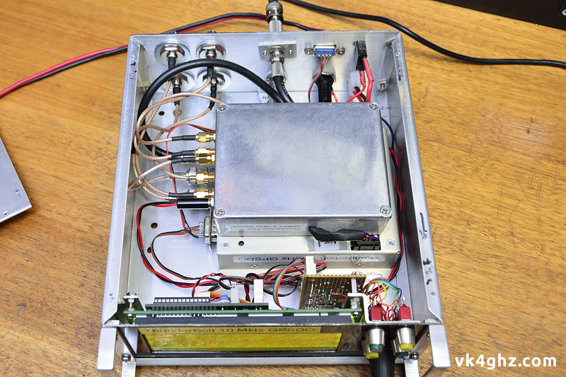
Inside, and piggybacked to the Thunderbolt itself, is a case containing a Down East Microwave 10-4 10 MHz splitter/filter kit and a Futurlec PSU for the ThunderBolt.
This arrangement remains unchanged when it was mounted inside the transverter box, and was originally described in this article.
Front panel display unit only requires two connections, and is easily disconnected.
A 2-way header for power, and a 3-way header for serial RS-232 data in & out.
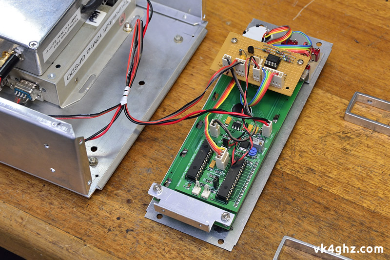
The sub-assembly constructed on veroboard is the “ThunderBolt Commander” project, and piggybacks via M3 tapped spacers onto the mounting arrangement.
For a cleaner look, I prefer not to have fugly mounting bolts visible from the front panel, so a “Z” bracket is used to mount one side of the ThunderBolt Display unit, with the switches passing through the Z bracket. M3 nuts used as spacers for the appropriate offset.
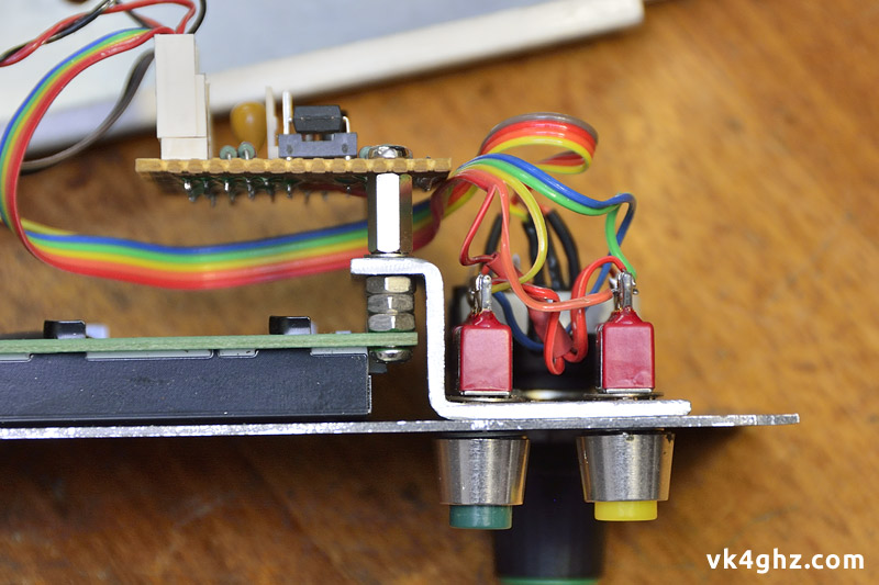
From the front, no visible LCD mounting screws.

Pushbuttons at the top select Full Position 3D, or Over Determined Clock operating modes.
Lower left pushbutton toggles between GPS time and UTC time.
Pushbutton lower right will initiate a survey.
ThunderBolt Display page select rotary switch below, with page number indicated bottom right on the LCD.
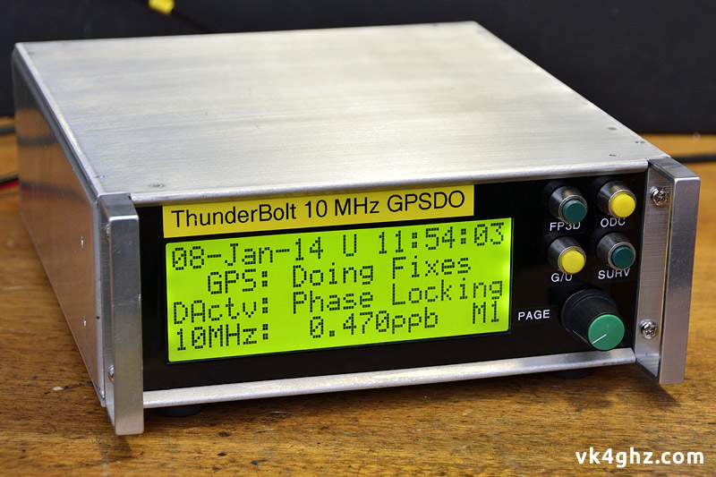
6mm white on black tape used for quick & easy labeling using a Brother “P-touch” label printer.
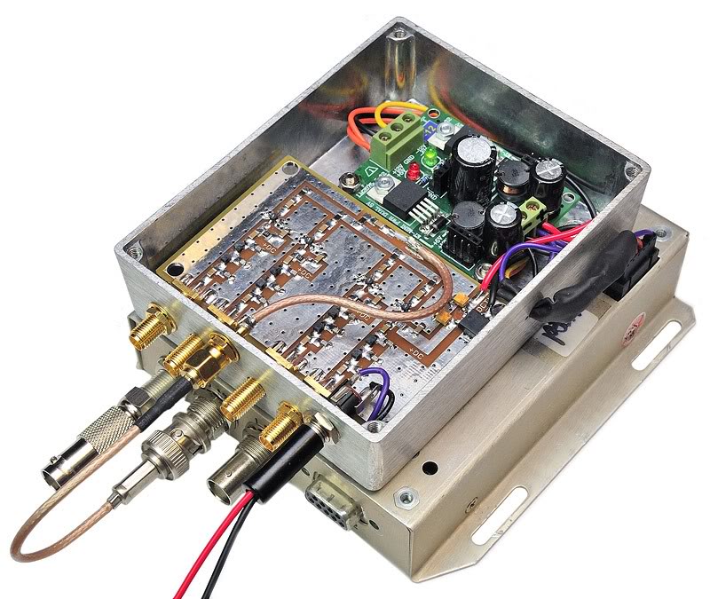
ThunderBolt’s antenna connector is an F connector, so it was decided to run an internal F to F patch lead (easy when using no-solder F connectors and RG-6 coax, as per satellite TV installations), and fit an inline F adapter on the rear panel, which becomes the antenna connector.
As a larger hole had already been prepared for a BNC connector, an adapter plate was required, in case you are wondering what the two M3 screws are for.
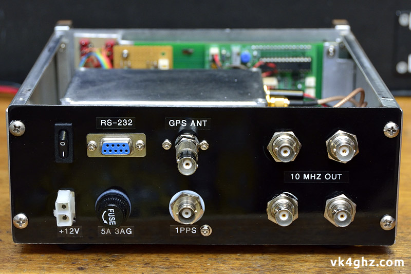
An F (m) to BNC (f) adapter is external to the case.
This bleeding obvious difference tends to makes it idiot-proof as to differentiate between an output and the input connector for the active GPS antenna!
Since the photo above was taken, the “10 MHz OUT” label was changed to read “10 MHz OUT +12dBm OUT” as a reminder of the output level on each of the four output ports.
The old and the new.
What was in the case, and what’s in there now.
Memories!
In 1990, labeling was that awkward “Letraset” crap, that cost a small fortune, especially if you wanted various font sizes.
There were three choices of lettering colour: black, black, or black.
Trivia: In 1990, the original GPS system was still five years away from being operational.
🙂