
Bugger!
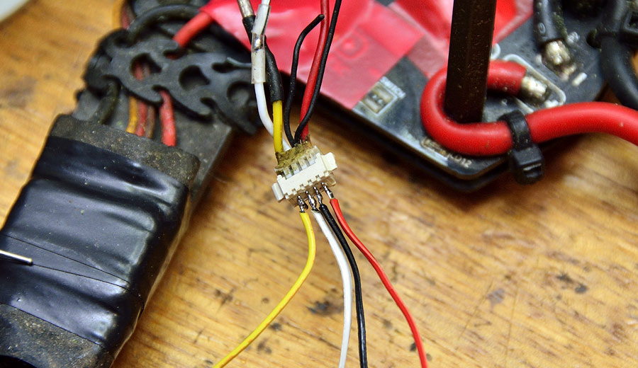
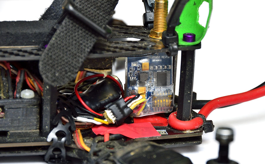
The Blackout Mini H Quad struck a tree branch just at the wrong angle, and dislodged the VTX (Video Transmitter).
A post-mortem at home found the connector was barely hanging onto the PCB and that two copper traces had been ripped off.
![]()
Not a right off, by any means!
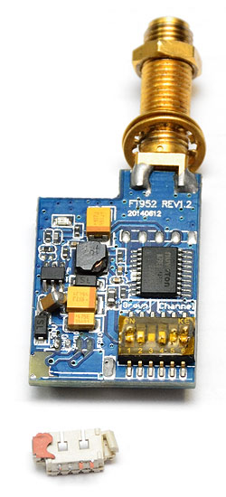
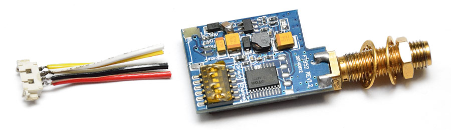
This VTX is a FT952 5.8 GHz 32 channel 200mW, although measured on the HP8562A spectrum analyzer, it puts out a healthy 290mW.
First, de-solder the remaining wires, and carefully remove the remains of the lifted copper traces.
Clean the board with IPA cleaner and a soft toothbrush.
Next, we need to solder some matching colour wires to the connector, so it becomes a “flying lead” rather than a PCB mount connector.
It much easier to solder to, if the connector is plugged into the other end (rather than float around on the bench) as you are soldering to it:
With all four wires soldered to the connector, and trimmed to a nominal length, we can now individually heatshrink each one.
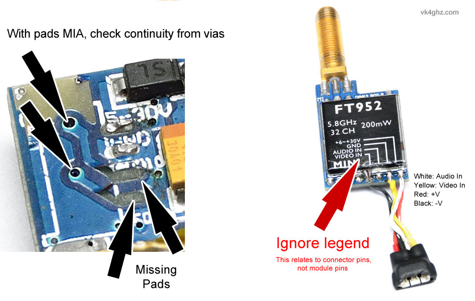
Use a multimeter on continuity range to determine which pins of the TX module the wires went to.
With some pads missing, the vias were a convenient point on the connector side of the board. Find the via by looking at the board and see where the copper trace ran.
Don’t be confused with the printed pinout legend on the other side, this applies the connector, not the actual TX module pins you see.
A layer of clear heatshrink is applied over the whole unit, then a second layer of clear heatshrink is applied around the wire entry point to minimise the wires being pulled off the PCB.
Cut out a section so the wires and connector body can pass through:
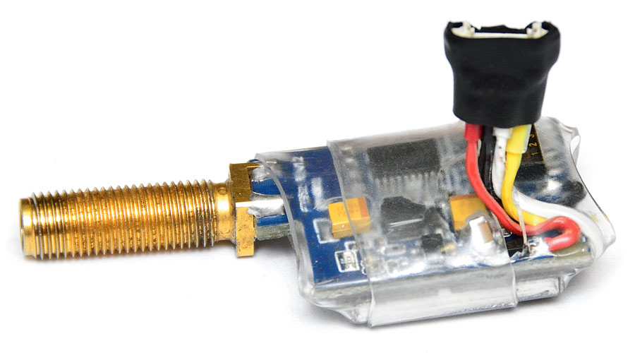
And reinstalled within the Blackout Mini H Quad:
🙂