Duplexers, discussion of techniques for 2m 600KHz offset where commercial cavity systems are rare.
Who are our experts in this field?
90% of our 2m repeaters are more than 30 years old now, who maintains the cavity systems?
Do we have national or state repeater maintenance and DR teams?
Noting, the hams who built the gear are well into retirement now.
http://www.vk6uu.id.au/cavity-filters.html
A good set of pictures, but what are the dimentions of the internal coupling loop?
I had a go and the results on 4 inch cavities are not that good.
Here is my testing and research:
http://www.unixservice.com.au/hamradio/ ... duplexers/
Note: 2m with 600KHz offset ie. 0.41% offsett is MUCH more difficult than 70cm with 1.14% offset (5MHz).
Alan VK2ZIW
Repeaters, Duplexer, BP/BR cavity construction
Re: Repeaters, Duplexer, BP/BR cavity construction
Hasn't modern test equipment made tuning filters so much easier than when that article was written?
I don't know if many of us build filters from scratch, I know I don't, but in this day and age with ever increasing site noise and the need to reduce antenna loads, understanding in how to correctly align and test filters has never been more important.
Cheers
Richard
VK2AAH
I don't know if many of us build filters from scratch, I know I don't, but in this day and age with ever increasing site noise and the need to reduce antenna loads, understanding in how to correctly align and test filters has never been more important.
Cheers
Richard
VK2AAH
-
VK7HH

- Forum Diehard
- Posts: 474
- Joined: Thu Sep 08, 2005 11:18 pm
- Location: Southern Tasmania
- Contact:
Re: Repeaters, Duplexer, BP/BR cavity construction
I do. Here is my 6M duplexer nearly complete.VK2AAH wrote: I don't know if many of us build filters from scratch
- 6M Duplexer
-
VK5PJ

- Forum Diehard
- Posts: 708
- Joined: Sat Apr 02, 2005 7:38 pm
- Location: Barossa Valley S.A
- Contact:
Re: Repeaters, Duplexer, BP/BR cavity construction
Hi Hayden
regards,
Looks very nice, certainly impressed meVK7HA wrote: I do. Here is my 6M duplexer nearly complete.
regards,
Peter Sumner, vk5pj
You have enemies? Good. That means you've stood up for something, sometime in your life.
- Winston Churchill
You have enemies? Good. That means you've stood up for something, sometime in your life.
- Winston Churchill
-
VK7HH
- Forum Diehard
- Posts: 474
- Joined: Thu Sep 08, 2005 11:18 pm
- Location: Southern Tasmania
- Contact:
Re: Repeaters, Duplexer, BP/BR cavity construction
Not finished yet Peter. Just waiting on some connectors from the US. That's an old photo too. Silver mica capacitors have been put in there now to improve the pass response.VK5PJ wrote:Hi Hayden
Looks very nice, certainly impressed me
regards,
Over 90dB of reject for about 1.2dB pass loss each side.
Re: Repeaters, Duplexer, BP/BR cavity construction
Hayden,
Are you running a notch-notch configuration or a pass/notch-pass/notch configuration?
I recall playing around with filters made from LDF5-50, using a single pickup loop we could make a very good notch, while with two loops fed appropriately we could get a good pass response.
Using say two pass filters and a notch on the TX side, and the same on the RX side, we were able to easily get 1 MHz separation at 52/53 MHz.
One thing to be careful of is that at sites where there are multiple services is that you really need to use bandpass filters on all receivers and transmitters, using only notch-notch duplexers means that there is very little, if any annenuation at other frequencies. This can cause intermodulation in your TX PA other base stations transmit.
What you have there looks quite good! Great to see people building their own.
Tim, VK4TIM.
QG62MM, Brisbane.
QG62MM, Brisbane.
Re: Repeaters, Duplexer, BP/BR cavity construction
Nice job Hayden.VK7HA wrote:
I do. Here is my 6M duplexer nearly complete.
-
VK7DB
Re: Repeaters, Duplexer, BP/BR cavity construction
I'd like to know more about the 6m pass filter made from heliax..
-
VK7HH
- Forum Diehard
- Posts: 474
- Joined: Thu Sep 08, 2005 11:18 pm
- Location: Southern Tasmania
- Contact:
Re: Repeaters, Duplexer, BP/BR cavity construction
Hi TimVK4TIM wrote:Hayden,
Are you running a notch-notch configuration or a pass/notch-pass/notch configuration?
It is the standard notch-notch type arrangement. I too am interested in your pass filters made from heliax.
These were made from LDF-750.
Thanks. I am well aware of that fact, and if the need arises a bandpass filter will be implemented. Testing needs to occur first. There are not too many receivers at our site, so I suppose that is one advantage. A circulator is much more effective to stop mixing in our PA.One thing to be careful of is that at sites where there are multiple services is that you really need to use bandpass filters on all receivers and transmitters, using only notch-notch duplexers means that there is very little, if any annenuation at other frequencies. This can cause intermodulation in your TX PA other base stations transmit.
What you have there looks quite good! Great to see people building their own.
Re: Repeaters, Duplexer, BP/BR cavity construction
Hi Hayden,
I forgot to ask... have you noticed any detuning due to temperature and moisture? I would have thought that this could be an issue in your mild climates.
Cheers
Richard
I forgot to ask... have you noticed any detuning due to temperature and moisture? I would have thought that this could be an issue in your mild climates.
Cheers
Richard
-
VK7HH
- Forum Diehard
- Posts: 474
- Joined: Thu Sep 08, 2005 11:18 pm
- Location: Southern Tasmania
- Contact:
Re: Repeaters, Duplexer, BP/BR cavity construction
Hi Richard,VK2AAH wrote:Hi Hayden,
I forgot to ask... have you noticed any detuning due to temperature and moisture? I would have thought that this could be an issue in your mild climates.
Cheers
Richard
Individual filters drift only a small bit, but the overall notch width is wide enough that it isn't a problem.
I've only had it in the shed, but it's been pretty good. Most of the time it's because I've heated the assembly up with a blowtorch.
Re: Repeaters, Duplexer, BP/BR cavity construction
A revelation that was not discovered reading the literature.
The type of cavity 1st in line after the antenna "T" split.
Does it matter, well it sure does.
We want ALL the power coming down the Rx path to get there.
To this end, we want the impedance at the 1st Tx cavity, at Rx frequency, very low
and after a 1/4 wave line presents as a high impedance at the antenna "T".
And conversely, the Tx signal doesnt want to see a bad SWR at the antenna "T"
because of the Rx cavity's impedance.
So cavity types that don't present as very low impedance at the "notch" frequency
will give us a headache figuring out the correct coax length to convert their infinite SWR
to a High Impedance to present at the antenna "T".
Obviously, in the cavity type with a series tuned single loop, it presents a very low impedance
at it's "T". This is also true of the heliax resonator as in Hayden's pictures.
I now have to rebuild at least two of my cavities in my blog:
http://www.unixservice.com.au/hamradio/ ... notes.html
80
Alan VK2ZIW
-
VK3TU
Re: Repeaters, Duplexer, BP/BR cavity construction
There's a great article on theory, operation and testing of duplexers here: http://ve2azx.net/technical/ve2azx-duplexerinfo.pdf It covers most designs and has a thoroughly good explanation of how they work. I found it very useful when I refurbished a Telewave 1486 duplexer (6 x 8in series tuned notch loop) we installed at the Club's repeater site (VK3RGL). The Telewave replaced a W1GAM design (6 x 4in cavity pass/reject) that we installed 30 years ago and that I've now also refurbished and modified. I had some previous experience with the pass/reject duplexer that the Telewave replaced and some band pass duplexers, but I hadn't dealt with series tuned loop duplexers before and didn't really know what to expect. The VE2AZX article answered many, many questions.
This is the Telewave during installation at RGL:
The square cavities on the bottom left are a pair of 10in aperture coupled receive filters and the top two are transmit filter for RGL repeater and RGL 2m beacon respectively. For comparison, the small cavity on the right hand side is the old 4 in TCA cavity we had for the 2m beacon. You can see the Telewave takes up a bit of room!
This is the finished installation with TX circulators and semi-rigid coax distribution cabling in place after Nik 3BA did a bit of window dressing:
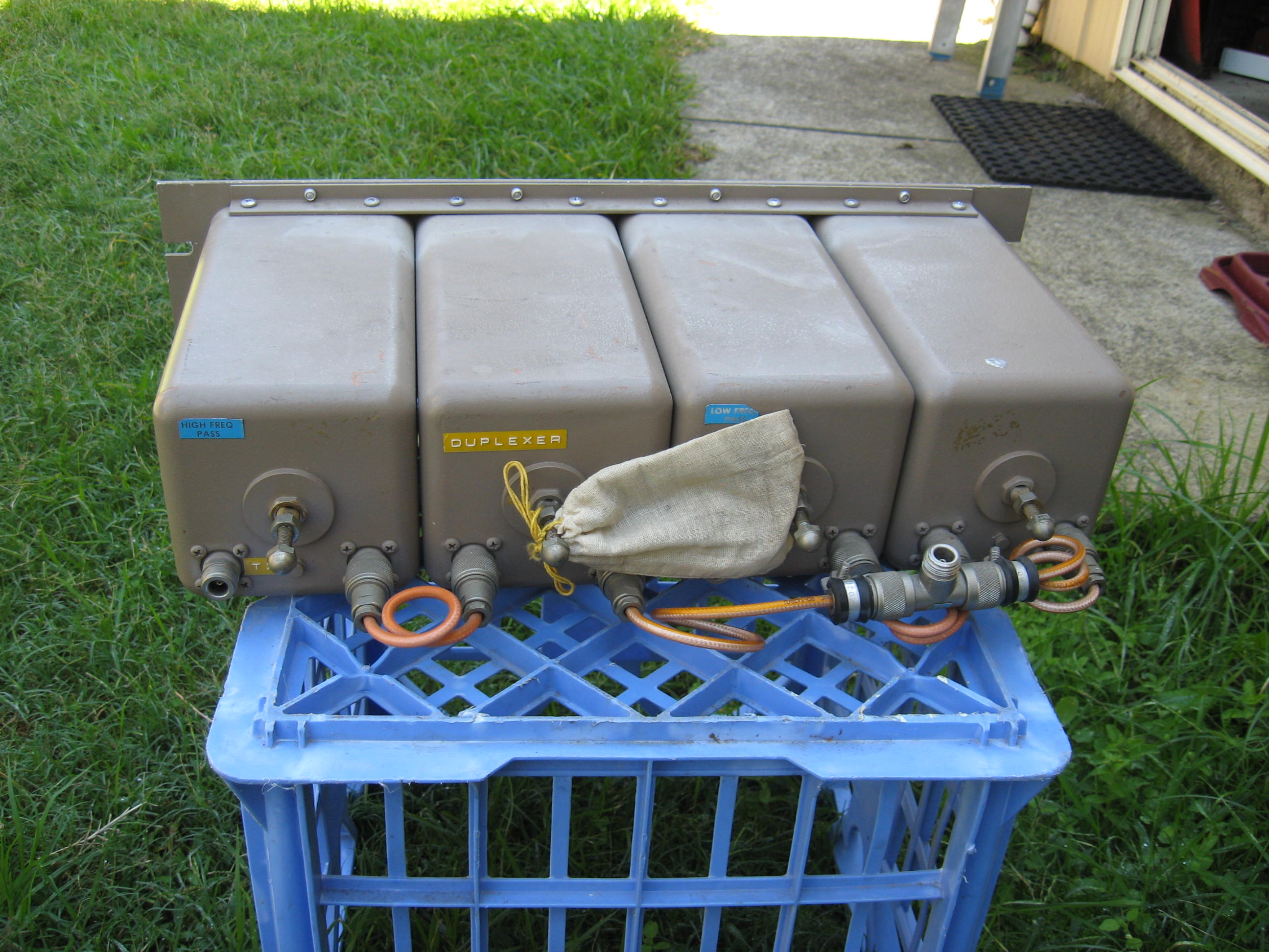
The old W1GAM duplexer that we'd been using for 30 years has now been refurbished, modified and repackaged for rack mounting:
The mods were to replace the floating Philips Mylar trimmers with Johanson porcelain types and rigidly mount them on Teflon mounts. I did this to all six cavities and got rid of the shunt L on the low pass/high reject cavities and used a larger value L (5t 1mm Cu enamelled wire, close spaced on 13mm former) with the Johanson trimmer in series. It gives you the ability to tune the notch as well as the cavity. I found the problem with using a fixed shunt L is that while you can set the 600KHz offset as you tune each cavity, once you string them all together, you need to dial in the notches by tuning each cavity again. And while you can get a reasonable compromise between insertion loss and rejection, the VSWR ends up suffering. Having the luxury of being able to tune the notches separately makes it much easier to tune and is worth the extra effort.
The internal arrangement in the boxes on the top of the cavities now looks like this:
Interconnect cables are the usual 7in RG-142 but corrected for N series connectors/Tee because the original used BNC connectors that turned a bit green over time. The cavity innards were still nice and shiny after 30 years of service and the duplexer still worked fine, but given it's being redeployed to another site, a birthday was probably a good investment. Insertion loss is around 1.7dB and rejection better than 110dB down each side (slightly better on the low pass side) and the VSWR is better than 1.1:1 on both.
Bert
VK3TU
This is the Telewave during installation at RGL:
- The "filter wall"
This is the finished installation with TX circulators and semi-rigid coax distribution cabling in place after Nik 3BA did a bit of window dressing:
- The finished "filter wall"
- ex-RGL duplexer
The internal arrangement in the boxes on the top of the cavities now looks like this:
- Modified C and LC shunts
Bert
VK3TU
-
VK2AVR
Re: Repeaters, Duplexer, BP/BR cavity construction
Thanks for linking that document Bert, hadn't seen it before!
Re: Repeaters, Duplexer, BP/BR cavity construction
BP/BR cavities
What is missing from the VE2AZX document above? http://ve2azx.net/technical/ve2azx-duplexerinfo.pdf
In this document is a picture, inside a 70cm cavity from 1976: http://www.cactus-intertie.org/LA/tec_not6.pdf
Energy coupling via magnetic or capacitive coupling creates both Pass-Notch and Notch-Pass types.
What are the advantages and implications in using this type of cavity?
1) Only one pass and notch frequency unlike the series coil/cap type
2) No complex parts, trimmer caps etc.
3) Everything inside the cavity, no external boxes.
Disadvantage
1) Line lengths between cavities and antenna "T" are not 1/4 wave. see: http://www.repeater-builder.com/motorol ... -notes.pdf
Re: Repeaters, Duplexer, BP/BR cavity construction
Well, I built the adjustable loops as per http://www.cactus-intertie.org/LA/tec_not6.pdf (above)
and they work, a treat. My loops are quite close, only 1mm apart. 5MHz pass-notch - yes.
I made the capacitive wire probes pictured in tec_not6.pdf but could not get anything useful
better than 20MHz pass-notch spacing.
Still need swapped pass-notch.
So, a little midnight dreaming, the "sense" of the magnetic coupling needed reversing, so I
put my loops down the cavity, not across. Success, but, down the cavity, the magnetic fiend is
not the same so the loops are not identical, so, some matching problems.
Has anybody tried a parallel resonant circuit inside the cavity?
I believe this is what is inside:
http://www.unixservice.com.au/hamradio/ ... lexer2.JPG
Under those trimmer covers, a trimmer, DOES NOT adjust notch spacing.
It adjusts an overall "stop band" about 40MHz wide, was centered on 480MHz.
I adjusted it down to 440MHz, then adjusted the plunger tuning which moved the "pass"
and "notch" together, as a pair down to 439/434MHz.
I sent this cavity set to Tassy before investigating further. (oh well)
Can anybody comment?
Alan VK2ZIW