Hi all,
I'm starting this thread to amalgamate all the info we have on the Spectrian amp boards that some of us have bought from Pyrojoe.
Just did some testing at 2403.1Mhz and with ~1w drive
At 26v and 12A it will put out 45.9 dbm which is about 39 watts
At 13.8v and 10A it puts out 41.6 dBm which is about 14watts
The only time I got ~60w out of it was near its design frequency of 2.3Ghz.
I''ve set the bias on the devices at 500mA each as per the data sheet for them.
Changing the bias to 2A per devices as per Pyro's advice does nothing to the power output.
Initial tests show the signal to be clean on the SA at 500mA per device. I'd have do some more testing to see if there is any measurable difference between the two bias settings.
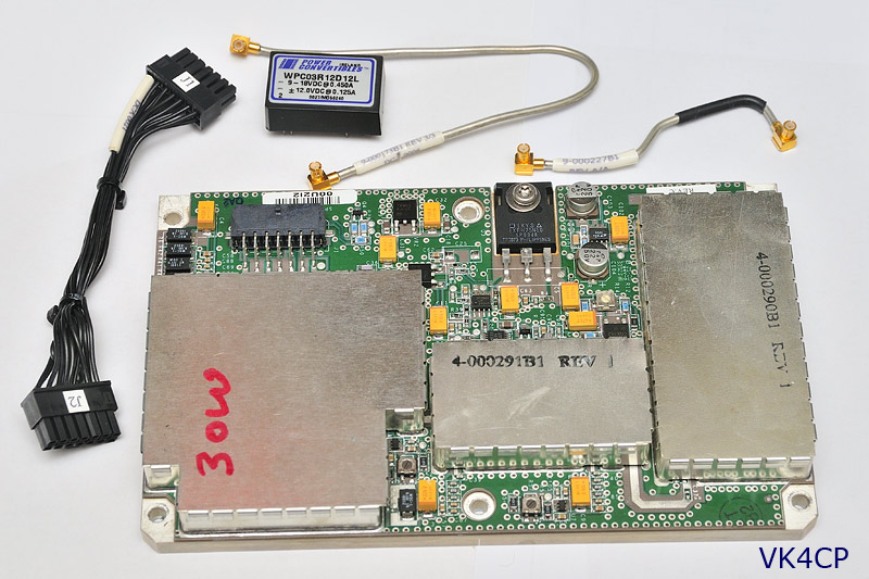
I've included a pic of mine below for comparison just in case there is more than one version of this board.
I've also included a drilling template that mates with a common Jaycar heatsick to make mounting easier for those who have not done that yet. Print it out 1:1 then cut it out and stick it to the top of the heatsink and use a centre punch to make your marks for drilling.
I'm going to do some more detailed testing and add pics and graphs.
regards
Tim
The Spectrian Amp for 2.4 GHz
The Spectrian Amp for 2.4 GHz
- Attachments
-
- The Spectrian amp pallet
-
- Spectrian-Amp-drill-template.pdf
- Drilling Template
- (26.95 KiB) Downloaded 292 times
-
--
VK2XAX :: QF56if23 :: BMARC :: WIA :: AMSAT-VK
VK2XAX :: QF56if23 :: BMARC :: WIA :: AMSAT-VK
-
VK7HH

- Forum Diehard
- Posts: 474
- Joined: Thu Sep 08, 2005 11:18 pm
- Location: Southern Tasmania
- Contact:
Re: The Spectrian Amp for 2.4Ghz
All good Tim,
As per the other thread, mine will be arriving shortly.
Also had some information from Andre VK4KAY on them -
As per the other thread, mine will be arriving shortly.
Also had some information from Andre VK4KAY on them -
I'm thinking I might get the same heatsink that Andre suggested from Altronics and maybe use hardline instead of SMA connectors.Hayden
the amps run very hot - they are not efficient. I run the amp at 26V.
You need a BIG heatsink (low thermal resistance) and a high speed -
large volume fan - to cope with the heat dissipation properly.
Dont underestimate!
Of course having said that I live alot further north and my shack temp
today will be 32deg inside and 40deg outside. But i can ragchew and
make it alarm quite often in winter.
I use the temp monitoring built into the board to feed to a
microprocessor which controls the fan. I also use a 2nd sensor on the
heatsink.
I have the fan cut in at 30degC, put up an alarm at 50degC and turn the
fan off at 27degC. The sensor on the spectrian board outputs in
degFahrenheit.
I used this heatsink - the entire 300mm of it!! Thus I needed to use a
brass support on the output connector to lift it above the heatsink surface.
I did use the same heatsink but cut to correct length initially - but of
course it heats up alot faster. So i opted for more difficult mounting
option.
https://www.altronics.com.au/p/h0545-30 ... -heatsink/
I used this fan blowing onto the heatsink (it is quiet loud due to air
noise but i dont care as it needs to cool, i use a second fan to suck
air out of the case.)
https://www.altronics.com.au/p/f1160-su ... aring-fan/
You may consider using this product with fans mounted at each end
drawing air in one end and out the other, but without the fans the
heatsink is NOT as good as above.
https://www.jaycar.com.au/fan-assisted- ... g/p/HH8530
Of course heatsink paste is required.
Re: The Spectrian Amp for 2.4Ghz
Very timely that this string appeared right now.
We have a number of these boards here in VK4. Information received - but I stress not acted upon yet - suggested that significant improvement in performance was possible by snowflaking the input circuit for 2.4. I understood that the output tuning was already good enough with little improvement to be had
We have a number of these boards here in VK4. Information received - but I stress not acted upon yet - suggested that significant improvement in performance was possible by snowflaking the input circuit for 2.4. I understood that the output tuning was already good enough with little improvement to be had
Kevin (KJ) VK4UH
Brisbane
Brisbane
Re: The Spectrian Amp for 2.4Ghz
Very interesting, do you have information on the snowflaking ?VK4UH wrote:Very timely that this string appeared right now.
We have a number of these boards here in VK4. Information received - but I stress not acted upon yet - suggested that significant improvement in performance was possible by snowflaking the input circuit for 2.4. I understood that the output tuning was already good enough with little improvement to be had
thanks
Tim
--
VK2XAX :: QF56if23 :: BMARC :: WIA :: AMSAT-VK
VK2XAX :: QF56if23 :: BMARC :: WIA :: AMSAT-VK

Re: The Spectrian Amp for 2.4Ghz
Whilst these big amps look really nice it can be hard to provide a good supply for them when operating portable. When looking around for an amp for my portable system I found Joe also had these amps. Right supply voltage, plenty of gain and readily made 30W at 13.8V. The nice thing is they're almost completely self contained and also have a circulator in the OP. They weren't so expensive a few years ago but what can you do?
Lou - VK3ALB
Being right doesn't excuse bad behaviour
Being right doesn't excuse bad behaviour
Re: The Spectrian Amp for 2.4Ghz
Hi all,
i've found a comprehensive test of the Spectrians at various voltages and biases here...
http://f1chf.free.fr/F5DQK/2_Amplis_RF_ ... 3xx%20Mhz/
You just need to be able to read French or use google translate.
Very interesting results!
regards
Tim
i've found a comprehensive test of the Spectrians at various voltages and biases here...
http://f1chf.free.fr/F5DQK/2_Amplis_RF_ ... 3xx%20Mhz/
You just need to be able to read French or use google translate.
Very interesting results!
regards
Tim
--
VK2XAX :: QF56if23 :: BMARC :: WIA :: AMSAT-VK
VK2XAX :: QF56if23 :: BMARC :: WIA :: AMSAT-VK
-
VK7HH
- Forum Diehard
- Posts: 474
- Joined: Thu Sep 08, 2005 11:18 pm
- Location: Southern Tasmania
- Contact:
Re: The Spectrian Amp for 2.4Ghz
Hi Lou,
Yes I did consider those other amps you posted too.
The 75W amps will work at 12V, although with less output power of course. I’ve been contemplating maybe using a 12V to 24V DC-DC converter for portable if I wanted to run at full output.
Hayden
Yes I did consider those other amps you posted too.
The 75W amps will work at 12V, although with less output power of course. I’ve been contemplating maybe using a 12V to 24V DC-DC converter for portable if I wanted to run at full output.
Hayden
-
VK7HH
- Forum Diehard
- Posts: 474
- Joined: Thu Sep 08, 2005 11:18 pm
- Location: Southern Tasmania
- Contact:
Re: The Spectrian Amp for 2.4Ghz
Another link of interest I found this morning on these amps:
http://www.chavfreezone.me.uk/2006-spectrian.html
I think I'll mount mine to the biggest heatsink I can find that will fit in my case, then use the onboard temperature control to drive a voltage controlled switch board to turn fans on/off.
Hopefully on SSB it won't be as much of a problem, but for digital modes I'll certainly need to watch it.
The 30W Class A boards are a little more expensive, pesky dollar.... but 13-14V @ 10A is still only 21% efficient for 30W output.
The 75W boards have a current draw of 12A for 25W out or 15% efficiency. Horses for courses I guess, you just save $50. We got our boards even cheaper as we got three, so splitting postage three ways.
Re: The Spectrian Amp for 2.4Ghz
Hi Hayden,
I cut about 220mm off a bit of Unilab KL series heatsink and bolted it to the top of one of those nice Jaycar steel project cases. Cut a hole in the lid and fixed the amp directly to the heatsink. I ran about 20 mins of 45wpm dits at full power and the temp rose but not much. HS was only warm to the touch. I'm sure there will be some dead KL's around in Launceston if not close to you.
I cut about 220mm off a bit of Unilab KL series heatsink and bolted it to the top of one of those nice Jaycar steel project cases. Cut a hole in the lid and fixed the amp directly to the heatsink. I ran about 20 mins of 45wpm dits at full power and the temp rose but not much. HS was only warm to the touch. I'm sure there will be some dead KL's around in Launceston if not close to you.
Lou - VK3ALB
Being right doesn't excuse bad behaviour
Being right doesn't excuse bad behaviour
Re: The Spectrian Amp for 2.4Ghz
Hi,
I have had a lot of experience with the Spectrian boards and the class A driver stage.
Note what Tim said in the initial post. Setting the bias on each of the three devices to 500ma, instead of the 2 amps recommended, is a definite strategy worth pursuing. The linerarity does not suffer appreciably as Tim found with his Spectrum analyser.
The lower level of power dissipation of 3 x 26volts x 2 amps (156 watts) versus 3 x 26 volts x 0.5 amps is very significant. (39 watts)
***************
On another note, I have found the tunnel style heatsinks that Jaycar and Altronics
https://www.altronics.com.au/p/h0515-he ... -heatsink/
sell are well worth the extra space that they take up - definitely worth looking at to suit some ways in which you might package the amplifier.
Cheers
Peter VK3QI
Re: The Spectrian Amp for 2.4Ghz
I can also vouch for the Spectrian 30W "driver board".
Plug and play.
What was received from PyroJoe circa January 2011:
I never tweaked the bias, nor thought of snowflaking, so this topic will be great reference material when I can find some time later in the year to have a play.
As others here have noted, being a class-A device, it's power hungry at idle.
One thing I did, was install an automotive relay, so that the +12V feed to the Spectrian amp was only applied during TX.
This saved wasting power during receive.
Doing this alone meant that heat build up was never an issue.
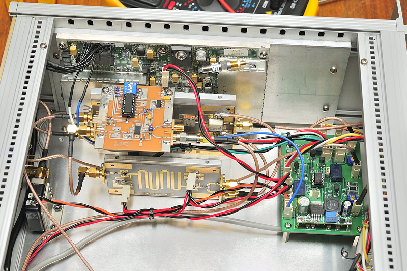
With conversational SSB, I found an extra slab of 1/4" aluminium bar was sufficient heat sinking, as you will see in my installation below.
(Note: I added the automotive relay after this picture was taken)
I would imagine digital modes would necessitate better thermal cooling!
Plug and play.
What was received from PyroJoe circa January 2011:
I never tweaked the bias, nor thought of snowflaking, so this topic will be great reference material when I can find some time later in the year to have a play.
As others here have noted, being a class-A device, it's power hungry at idle.
One thing I did, was install an automotive relay, so that the +12V feed to the Spectrian amp was only applied during TX.
This saved wasting power during receive.
Doing this alone meant that heat build up was never an issue.
With conversational SSB, I found an extra slab of 1/4" aluminium bar was sufficient heat sinking, as you will see in my installation below.
(Note: I added the automotive relay after this picture was taken)
I would imagine digital modes would necessitate better thermal cooling!
Adam, Brisbane
vk4ghz.com
VK4GHZ on Youtube
VK4GHZ on Odysee
10 things that happen when you stop checking Facebook constantly: http://tiny.cc/t5h7cz
How to quit Facebook: https://www.consumerreports.org/social- ... -facebook/
vk4ghz.com
VK4GHZ on Youtube
VK4GHZ on Odysee
10 things that happen when you stop checking Facebook constantly: http://tiny.cc/t5h7cz
How to quit Facebook: https://www.consumerreports.org/social- ... -facebook/
-
VK7HH
- Forum Diehard
- Posts: 474
- Joined: Thu Sep 08, 2005 11:18 pm
- Location: Southern Tasmania
- Contact:
Re: The Spectrian Amp for 2.4 GHz
Thanks Adam,
I did see your posts on your website using the 30W driver board.
Excellent idea on the automotive relay, I think I'll go down the same route. I have one on the bench here ready.
I did see your posts on your website using the 30W driver board.
Excellent idea on the automotive relay, I think I'll go down the same route. I have one on the bench here ready.
Re: The Spectrian Amp for 2.4Ghz
I'm doing exactly that.VK7HH wrote: I think I'll mount mine to the biggest heatsink I can find that will fit in my case, then use the onboard temperature control to drive a voltage controlled switch board to turn fans on/off.
I didn't feel like reinventing the wheel so I used a Jaycar kit of a Silicon Chip article, https://www.jaycar.com.au/universal-vol ... h/p/KC5377 to do the job.
It turns on 40C and turns off at 30C
cheers
Tim
--
VK2XAX :: QF56if23 :: BMARC :: WIA :: AMSAT-VK
VK2XAX :: QF56if23 :: BMARC :: WIA :: AMSAT-VK
Re: The Spectrian Amp for 2.4 GHz
You don't need it for our boards.VK7HH wrote:Thanks Adam,
I did see your posts on your website using the 30W driver board.
Excellent idea on the automotive relay, I think I'll go down the same route. I have one on the bench here ready.
You can leave V+ connected to the board all the time since no bias is present until pin 2 is taken to +12v ( ONLY +12v - that includes when you are using a 26V buss )
In fact you want V+ all the time so you have a signal on the temp out pin 1. i.e. No V+, no temp out, no fan driver !!
BUT.... I still use a 12V automotive relay driven from a small SMPS to switch the high current side of the transverter on.
I use both a 12V and 5V SMPS to drive all the main circuitry of the transverter with only the PA connected to the input V+.
This means I can run my transverter from either 13.8v or 26V if I want QRO
For portable ops I will be using a 12Vto24V 500W SMPS.
regards
Tim
Last edited by VK2XAX on Sat Jan 26, 2019 3:35 pm, edited 1 time in total.
--
VK2XAX :: QF56if23 :: BMARC :: WIA :: AMSAT-VK
VK2XAX :: QF56if23 :: BMARC :: WIA :: AMSAT-VK
Re: The Spectrian Amp for 2.4 GHz
Hi all,
If you don't feel like soldering wires to the 10 pin connector to get at the temp, enable and bias pins I have found that this connector from Element14 fits nicely.
https://au.element14.com/jst-japan-sold ... dp/1830783
Don't forget to order the matching pins to fit the connector SPHD-002T-P0.5
regards
Tim
If you don't feel like soldering wires to the 10 pin connector to get at the temp, enable and bias pins I have found that this connector from Element14 fits nicely.
https://au.element14.com/jst-japan-sold ... dp/1830783
Don't forget to order the matching pins to fit the connector
regards
Tim
--
VK2XAX :: QF56if23 :: BMARC :: WIA :: AMSAT-VK
VK2XAX :: QF56if23 :: BMARC :: WIA :: AMSAT-VK
-
VK7HH
- Forum Diehard
- Posts: 474
- Joined: Thu Sep 08, 2005 11:18 pm
- Location: Southern Tasmania
- Contact:
Re: The Spectrian Amp for 2.4Ghz
Hey Tim,VK2XAX wrote:
I didn't feel like reinventing the wheel so I used a Jaycar kit of a Silicon Chip article, https://www.jaycar.com.au/universal-vol ... h/p/KC5377 to do the job.
It turns on 40C and turns off at 30C
That's exactly what I used. I picked one up yesterday and have it setup ready to go. The board outputs 10mV/degree fahrenheit. So 40 degrees will be 1040mV and using the hysteresis pot it should turn off at 860mV (30 degrees C). Good stuff, nice and easy.
What SMPS are you using for 24V > 12V. I ordered some little boards to switch my Transco coaxial relay, but then realized they are actually step down boards, so I might reverse my thinking and use them to power my transverter and everything else 12V as the current draw will be low. The boards can do 3A apparently.
Just laying out where to place all my bits in the case.. I think I need to upgrade my heatsink to the "channel" one with fans each end.
Re: The Spectrian Amp for 2.4Ghz
Hi Hayden,VK7HH wrote: What SMPS are you using for 24V > 12V. I ordered some little boards to switch my Transco coaxial relay, but then realized they are actually step down boards, so I might reverse my thinking and use them to power my transverter and everything else 12V as the current draw will be low. The boards can do 3A apparently.
Just laying out where to place all my bits in the case.. I think I need to upgrade my heatsink to the "channel" one with fans each end.
As for SMPSs I used something like this...
https://www.ebay.com.au/itm/DC-DC-LM259 ... 2731049649
My antenna relay is 24v but I'm driving that from 12v too using the first circuit in my photo blog for 2.4Ghz here...
https://photos.app.goo.gl/4mVCWhHF8yfzTSbR9
There are two circuits, one that switch on +Ve and the other when grounded. It just depends on how you want to drive your relay.
I decided that I wanted the antenna relay to be switched on receive so with power off the PA is connected to the antenna, not the LNA.
It also means that the antenna relay is the first item that is switched so its never switched hot.
regards
Tim
--
VK2XAX :: QF56if23 :: BMARC :: WIA :: AMSAT-VK
VK2XAX :: QF56if23 :: BMARC :: WIA :: AMSAT-VK
Re: The Spectrian Amp for 2.4 GHz
Hi all,
So here is some definitive tests on the Spectrian amp board at 2.4Ghz
I wrote a small program in LabView to collect out put from my HP438A power meter while simultaneously stepping the amplitude of my signal generator.
To get a maximum of 32 dBm drive I assembled a drive chain of a Gali84 driving my WiFi amp. I profiled the drive chain first to ensure they wouldn't colour the results.
I then did a series of 3 tests each at 13.8V and at 26v.
Test 1 - all FETs bias set at 600mA
Test 2 - Driver FET bias set at 2A
Test 3 - All FETs bias set at 2A
The data collected was then imported into Excel and graphed
While Pyro suggests setting the amp biases at 26V and then "its good to go" at 13.8v - I suggest that that is backwards if selecting the 2A/600mA/600mA bias config since at 13.8v the biases will drop making the final FETs bias around 450mA.
regards
Tim
See results of those tests in the attached files.
- Spectrian at 26V
- Spectrian at 13.8v
- LabView program
--
VK2XAX :: QF56if23 :: BMARC :: WIA :: AMSAT-VK
VK2XAX :: QF56if23 :: BMARC :: WIA :: AMSAT-VK
Re: The Spectrian Amp for 2.4 GHz
Great stuff Tim!
Imagine if you had posted that information onto a Facebook group - lost within a few days.
That is why having an archive of this forum is so useful.
Conclusion from the results? I would suggest with the earlier findings of IMD being -30dBc, it is well worth upping the drive a little above the 1 watt mark and running the biases around the 500 to 600 mA mark.
It certainly cuts down on the heat which one has to dissipate.
****************
The background to these boards is in the fact that Spectrian used 3 such boards in their amps to deliver 60 watts OUTPUT class A for an input of 0dBm in the analogue phone service. In other words they were only expecting 20 watts from each board (plus a small overhead for the NOVA isolators). If you have seen the heat sink that Spectrian went to the trouble to use for these amps, it is a machining work of art. Of course they ran off 48 volts with a Switch mode step down to 26 volts on board.
****************
For the doubters here is the data sheet for the XRF286S
https://www.digchip.com/datasheets/part ... 6S-pdf.php
Functional tests at 2GHz Idq of 500mA Vdd of 26 volts Efficiency 30% and IMD of -30dBc
Great stuff Tim!
Cheers
Peter VK3QI
-
VK7HH
- Forum Diehard
- Posts: 474
- Joined: Thu Sep 08, 2005 11:18 pm
- Location: Southern Tasmania
- Contact:
Re: The Spectrian Amp for 2.4 GHz
Thanks for your results Tim,VK2XAX wrote: While Pyro suggests setting the amp biases at 26V and then "its good to go" at 13.8v - I suggest that that is backwards if selecting the 2A/600mA/600mA bias config since at 13.8v the biases will drop making the final FETs bias around 450mA.
regards
Tim
So according to your data, Pyro's measurements are incorrect as per posting on the eBay listing, especially at 13.8V?
Psat is 30W. Required input power for 25W output is < 400MW