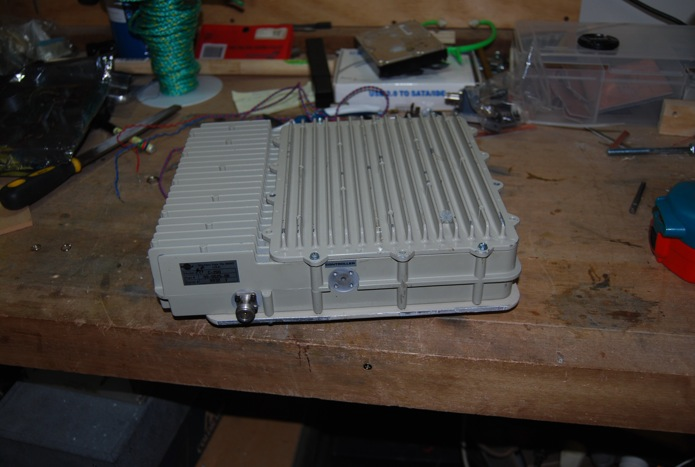
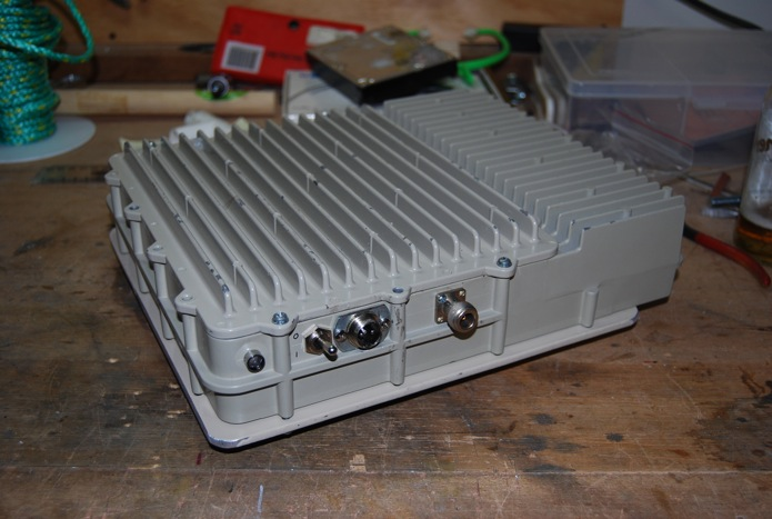
Here are some photos of my transverter that I have been building. It uses one of the vk3dxk kits for the transverter and the local osc is a mini kits osc running at 592mhz then x3 to 1776mhz using the board supplied by vk3dxk. I have mounted all of this in a power amp module which I gutted and modified to give me an output of around 30dbm.
The power amp with the covers on.
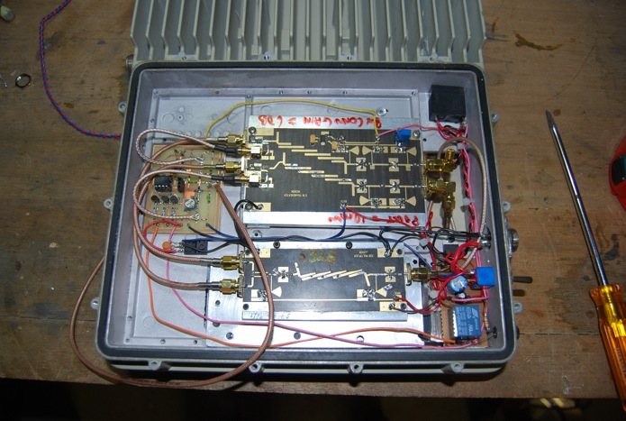
The vk3dxk transverter.
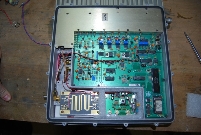
The power amp and bias control. The mini kits osc and x3 board mounted down the bottom.
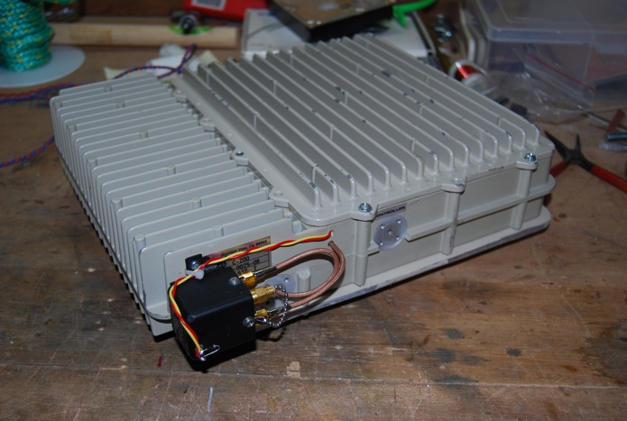
All that left to do if mount the output relay then I am finished. The only promble is the relay I have is 28v.
VK5TX
Ben
Last edited by VK5TX on Wed Dec 15, 2010 7:11 am, edited 1 time in total.
Triggering the relay only needs a 28V (or there abouts) pulse. Thereafter, 12V will hold it closed. There are simple circuits around employing an NE555 as a Voltage doubler to do just that. A quick Google should find it, but if you can't, let me know and I will find it for you. I use the same little circuit on my 28V relay on my 10GHz rig and it works great.
I just built this to test a theory and it works fine. The output is 22v with no load and drops to 16.5v with the relay activated. This is sufficient to hold the relay on.
73
Iain
VK5ZD
73
Iain Crawford - VK5ZD
Munno Para West, SA - PF95ih
This is what I use - it has about the lowest parts count possible.
R1 = 1K. C1 = 1000uF 25V. D1/2 = 1N4001. TR1 = BD139 or similar
Don't worry about the comment about V+. It's originally a relay speedup circuit. However, it quite happily runs 26V relays from 12V.
I've used this with 26V relays ranging from mini SMA to Transco Y (BIG!) and it hasn't missed a beat. With the Transco (which draws 0.23A per coil, and there are two coils!), I did a crude experiment to see how fast it would recharge by rapidly tapping two wires together. I couldn't get it to falter, even though it was probably switching at about 3-4 Hz - much faster than you'd ever need.
I made a sequencer using a 8 pin picaxe driving 3 outputs.
1. TX / RX change over and 8v for the TX / RX paths on the transverter boards.
2. Output relay.
3. A relay to turn the power on for the amp.
The amp I brought at a ham buy n sell for $20 and was used for 6Ghz TX only data link. So i removed some of the circuit boards and i am only using the power amp and the biasing board.
The amp was design to run 24 hours a day 7 days a week so the heat sink case is a bit of over kill for what I am using it for but I milled the case down so it is square and a little lighter. It was a big tight fitting every thing in as I didn't what to mount anything on the outside of the case but the change over relay I have is to big fit in so it will be mounted on the outside.
VK5TX wrote:I made a sequencer using a 8 pin picaxe driving 3 outputs.
1. TX / RX change over and 8v for the TX / RX paths on the transverter boards.
2. Output relay.
3. A relay to turn the power on for the amp.
Ben
VK5TX
ohh well done Ben,
wonder if you will publish that online or something so others may benefit the cct and the code
if you dont have a www site, I would be happy to put the info on my ham pages.
I have just completed some short range tests Ian VK5ZD and it appears I have a problem. When I TX the signal appears 20Khz lower that the RX frequency. The two paths share the same lo.
I think I have found the problem. When I TX a 2.8Mhz 200mV signal appears on the +ve supply rail and at the LO is around 40mV. I have put in 100nF caps on the power supplies to every board and the signal has dropped away.
Now I just need to do some more field tests to confirm every thing is good.
VK3HZ wrote:This is what I use - it has about the lowest parts count possible.
24V_Relay_Drive.jpg
R1 = 1K. C1 = 1000uF 25V. D1/2 = 1N4001. TR1 = BD139 or similar
Don't worry about the comment about V+. It's originally a relay speedup circuit. However, it quite happily runs 26V relays from 12V.
I've used this with 26V relays ranging from mini SMA to Transco Y (BIG!) and it hasn't missed a beat. With the Transco (which draws 0.23A per coil, and there are two coils!), I did a crude experiment to see how fast it would recharge by rapidly tapping two wires together. I couldn't get it to falter, even though it was probably switching at about 3-4 Hz - much faster than you'd ever need.
Regards,
Dave.
Hi Dave, Thank you for suggesting this simple solution, I knocked it up on some veroboard yesterday and it works well.
I am considering putting a reversed biased diode accross the relay coil to suppress the back EMF.
VK2KYP wrote:I am considering putting a reversed biased diode across the relay coil to suppress the back EMF.
Hi Gary
No need to - in fact, not recommended. D1, C1 & D2 provide back EMF protection, charging C1 at the same time. Putting a reverse diode across the relay would actually slow down the circuit.
Regards,
Dave.
Thanks Dave, The relay is a bit slow to release so I think I will reduce the C1 to 500 mfd.
The excellant results that 2.4 GHz has been producing recently, everbody should trying to get on as many microwave bands as possible.