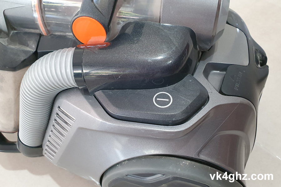
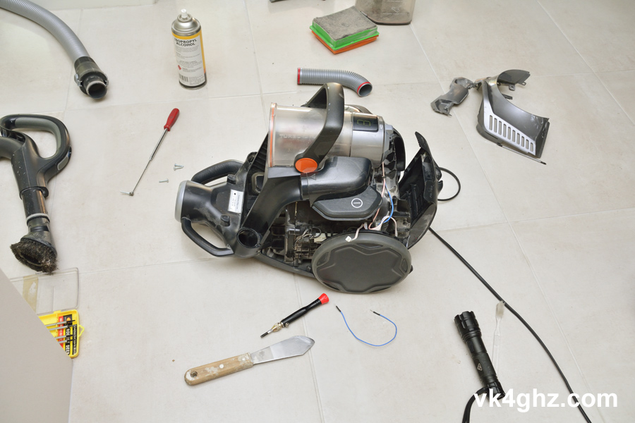
The power on/off switch on an Electrolux ZUF4205AF vacuum cleaner was becoming unreliable, and needed fixing or replacing.
Note that this repair is not aimed at the regular consumer, but somebody who has some basic electronics experience.
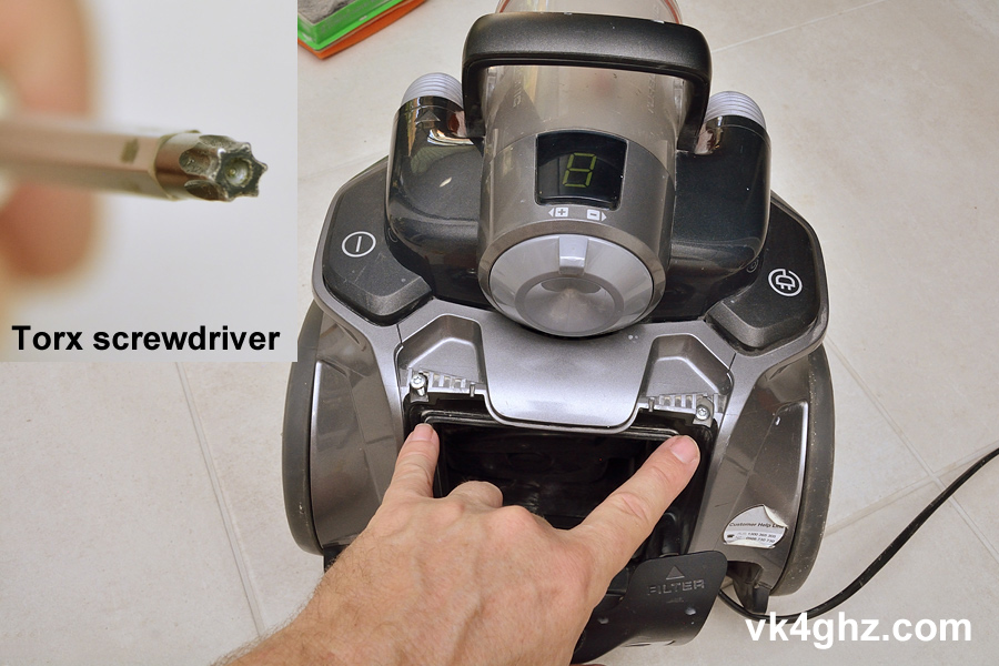
Remove the two Torx screws as indicated below, and remove the associated cover plate. It does come out with careful bending and twisting!
Remove the short tube, which is simply a push fit:

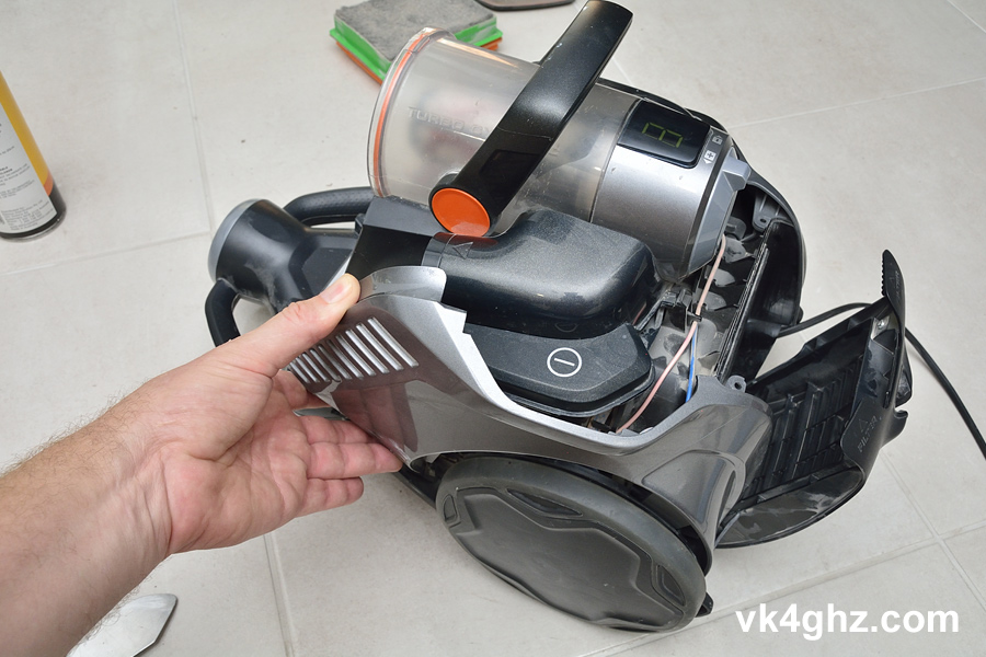
Now the awkward part, removing the side panel.
This panel basically clips into place.
I used a putty knife to lever the panel off around the clips, but a regular kitchen knife may do the job – just be careful you do not crack or break anything in the process.
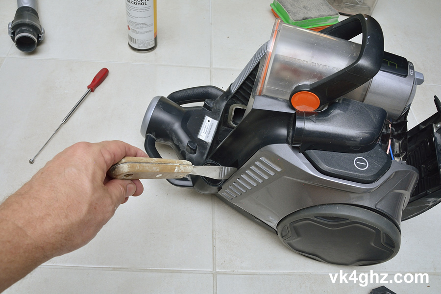
This is difficult to explain, but I found it easiest if the panel came off towards the rear. ie; in a clockwise sort of removal.
Do not attempt to lever the wheel off.
It’s worth noting, the power switch isn’t a real power switch that would switch 240VAC mains, rather, it’s a small tactile push button that (most likely) becomes an input to the cleaner’s microcontroller.
The microswitch is on a small PCB sub-assembly of it’s own.
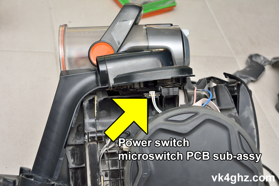
This PCB is held in on two sides with fingers moulded into the housing.
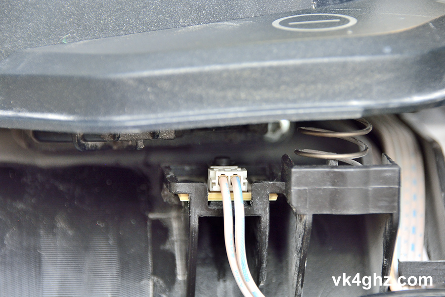
Being difficult to remove, I wanted to verify the switch was in fact the culprit first.
I attempted to clean the switch and the solder-side of the PCB using IPA (isopropyl alcohol) spray and a toothbrush.
As you can imagine there is quite a lot of dust inside this thing, and it was unknown if the microcontroller input was a high impedance where the dust on the solder-side could become a leakage path.
Cleaning with IPA did not improve the reliability.
The switch lead was unplugged from the PCB and I used a breadboard type jumper lead to simulate the switch.
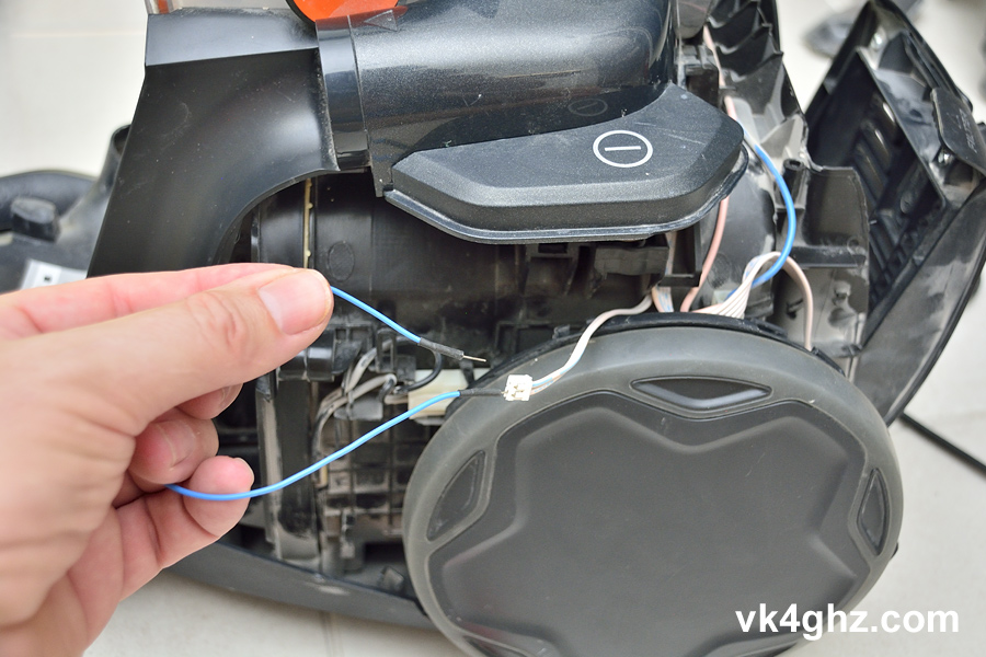
The vacuum cleaner was plugged into the mains, and I could reliably turn it on and off with the jumper lead, no problem.
Clearly, the microswitch would need to be replaced
At this point the mains lead was removed from the power socket.
It was too difficult to get any decent photos of how the PCB is retained, but you will see the two fingers in there.
I then used a small flat blade screw driver to carefully lever the PCB out on one side, and then it could be lifted out.
This is the microswitch sub-assembly, and the arrow indicates direction the PCB should be inserted, but this should be obvious considering the connector faces outwards.
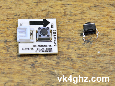
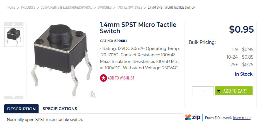
The tactile switch (6mm x 6mm x 1.4mm actuator with through-hole legs) is quite common and I purchased a replacement from Jaycar (electronics components retailer in Australia), costing $0.95. Cat No. SP0601.
https://www.jaycar.com.au/1-4mm-spst-micro-tactile-switch/p/SP0601
The original microswitch was de-soldered from the PCB, and the new microswitch soldered on.
Before fitting the PCB back into it’s spot, I plugged in the switch wiring connector, and plugged the vacuum back to the mains, and tested for correct operation.
Absolutely fixed!
Mains lead was disconnected, and the vacuum was re-assembled in the reverse order it was pulled apart. (umm, der!)
Now works just like new, and one hour well spent, considering it’s a $600 vacuum cleaner.
🙂