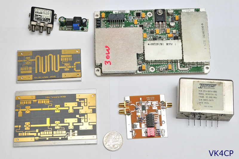
I’ve had an interest in microwaves for many years, but never knew quite how to kick start it off.
2.4 GHz seemed like a good place to start.
Let’s face it, finding information on how to get started on the microwave bands is difficult.
Most microwavers still, to this day, have a propensity to publish their knowledge in a ‘dead tree’ that you have to purchase, instead of publishing on the internet, where you can Google it.
Something to do with why younger generations aren’t getting into ham radio… just maybe?
#JustSayin
Components for my 2.4GHz system
eBay is great source of parts! You may have to dig around, but they are there. Remember, most of this stuff is only available from international sellers.
Whilst waiting for the VK3XDK 2.4GHz transverter kit to become available, in late December 2010 I started acquiring other parts I would need.
Grid pack antenna
I purchased a 24dBi grid pack from eBayer iConnect in Melbourne. $89.95 + $19.90 shipping. Delivery took 3 days.
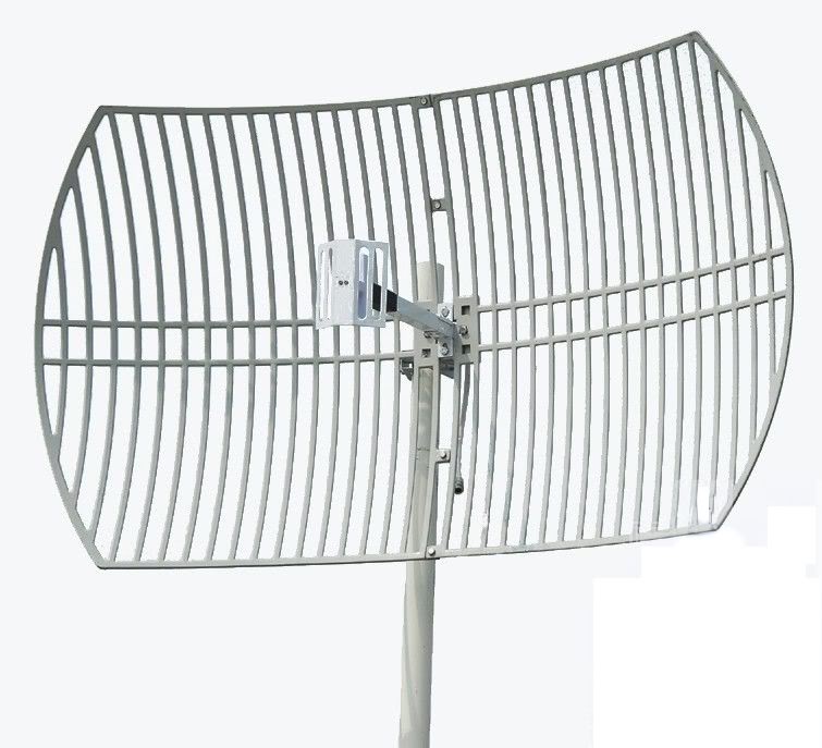
Above: 24dBi grid pack. This picture shows it in vertical polarization mode. Turn 90° for Horizontal polarization.
These are the solid cast aluminium type that come in two halves which simply bolt together. Ready to go on 2.4GHz. 😀 I think the cast type are more robust than the wire type, which becomes a consideration for Field Day use, where stuff can get knocked about.
Features/Specifications:
- Outdoor Grid Parabolic Dish Antenna
- Freq. Range: 2400-2483.5 MHz
- Bandwidth: 83.5 MHz
- Gain: 24 dBi
- Horizontal Beam-width: 10 degree
- Vertical Beam-width: 14 degree
- F/B Ratio: >= 30dBi
- V.S.W.R: < = 1.5
- Impedance: 50 ohm
- Polarisation: Vertical or Horizontal
- Max Power: 100 W
- Connector: N Female
- Dimension: 0.6×0.9 m
- Weight:2.0 kg
- Rated Wind Velocity :60 m/s
2.4Ghz Power Amplifier
A “Spectrian” 30W PA module was chosen, from pyrojoseph AKA Pyro Joe, KI4NPV in Florida.
These are the driver boards from a larger 180W Spectrian Power Amplifier, and are a perfect solution for a reasonable amount of power that can be directly driven by a typical transverter board.
Of course, you could consider one of the 60/75W PA Spectrian boards, but these require 1.25W of drive, so an intermediate driver amplifier would be required… too hard for now.
Joe is a great eBayer. I ordered my 30W PA on 21/12/10 and it arrived at my door on 4/1/11. Pretty darn good, considering it was over Xmas/New Year. He replies promptly to any email queries too – an absolute pleasure to deal with. 😀
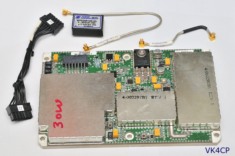
Above: 30W PA from PyroJoe. USD$145 + USD$20 for postage to Australia.
I/P drive: 10mW (10dBm) or less for 30W O/P Power O/P: 30W from 2.3GHz to 2.35GHz with a linear gain of 35dB. Mode: Class-A linear Power requirements: 13-14V @ 10A and + 24 to +28v bias @ 50mA.
SMA Coax Relay
Transco 919C70100 SMA “Failsafe” relays seem to be a popular choice, and are always available on eBay for nominally USD$20-$25 + postage. (Transco was actually taken over by Dow Key in the early 1990’s, so you will see identical products branded as both Transco and Dow Key.) These have a 28V coil, but don’t let that put you off, because 12V relays aren’t as common, and you will pay a premium for them.
DC-DC Step-up Converter
As mentioned above, 28V relays are plentiful and reasonably priced. For (normal) 12V operation you will need a step-up converter to activate the relays. The Spectrian PA board also requires 24-28V @ 50mA for bias, so why not use the one DC-DC step-up converter to drive both.
There are several options available, [url=http://www.w6pql.com/parts_i_can_provide.htm]W6PQL 12 to 28v Boost Regulator USD$25 + post[/url] comes to mind, however for USD$9.99 delivered you can get an [url=http://cgi.ebay.com.au/LM2577-DC-DC-Step-Up-Module-3-34V-4-35V-DIY-module-Z-/160505034634?pt=BI_Electrical_Equipment_Tools&hash=item255ed8778a]LM2577 based DC-DC step up converter ex China from eBayer wholesell-aa[/url].
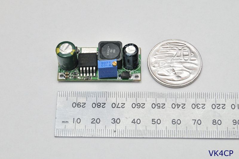
These are a cost effective way to generate an amp or so at 24-28V, although we only need 130mA. (50mA for Spectrian bias + 80mA for SMA relay) An LM2577 from Jaycar alone is $16.95, then you need all the other components too.
Being curious, I checked the output of this module on a CRO, where I observed 170mV of ripple @95kHz on its output. Instinctively, I set about to reduce this ripple, so I added a 0.047uF capacitor (which ended up being the optimum value) across the existing o/p electrolytic.
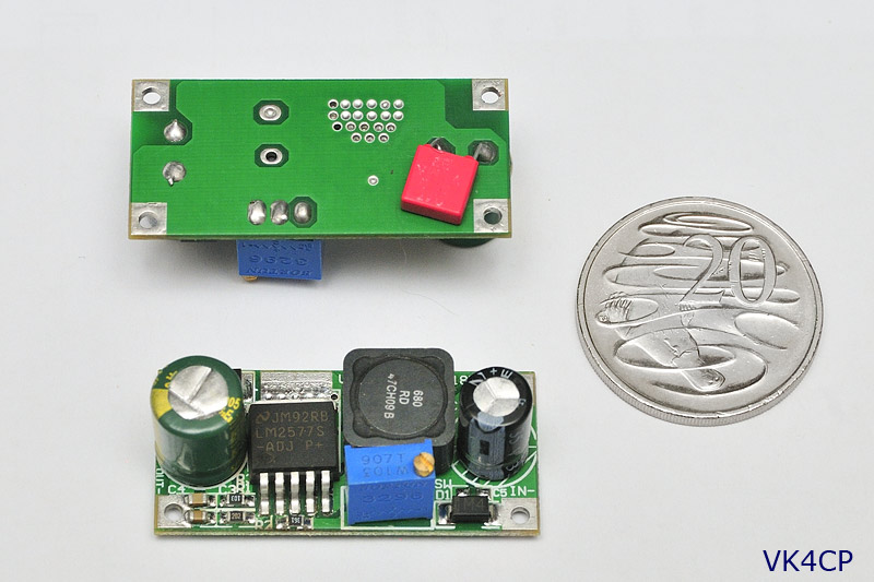
Above: PCB cleaner wiped off the lettering, but it’s a 0.047uF across the o/p electrolytic to reduce ripple.
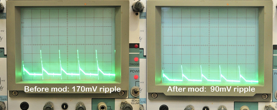
As it turns out, I was worrying about nothing, because when I asked PyroJoe if this ripple on the bias supply would effect the Spectrian board, he replied;
Hi Adam, This amount of ripple will have no effect at all. Joe
10MHz Reference Source
10 MHz will come from a Trimble ThunderBolt GPSDO system.
Let’s have a closer look at the VK3XDK products…
VK3XDK/VK3HZ Agile PLL Synthesized Local Oscillator
Because of the small and fiddly components on this board, Graham provides this as a pre-assembled board, $100 + $5 postage.
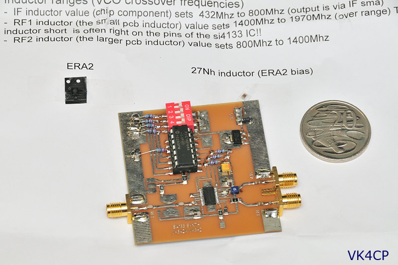
Above: VK3XDK/VK3HZ synthesized LO board. 4-way DIP switch allows selection of 16 pre-programmed frequencies.
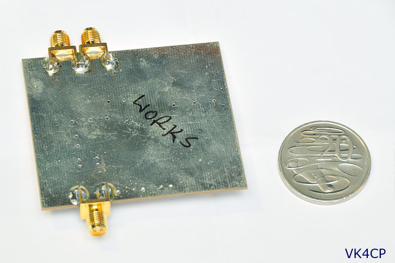
Above: Phew!!! This one was marked as “works”! 😉
All the PLL boards Graham supplies are pre-tested, so this takes a lot of the hassle out of generating a stable and on-frequency LO signal. The ISOTEMP 134-10 will be the 10MHz reference that the PLL board requires.
VK3XDK 2.4GHz Transverter Kit
General information on the VK3XDK series transverter boards can be found on the [url=http://www.vk9na.com/Transverters.html]VK9NA transverters page[/url]
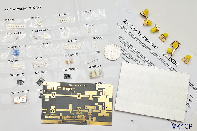
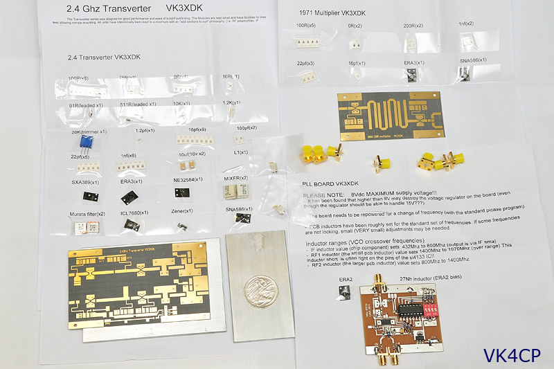
Above: The 2.4GHz kit. $150 + $10 postage.
All on-board parts are supplied, as well as an aluminium base-plate.
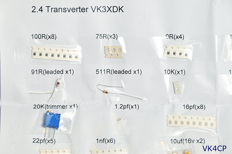
Above: Making it easy, VK3XDK provides all the parts in easy-to-identify format.
The PCBs are great quality and plated-through.
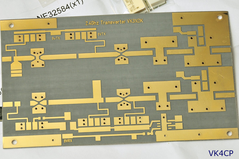
Above: Close-up of 2.4G transverter PCB
VK3XDK 1900-2100 Multiplier Kit
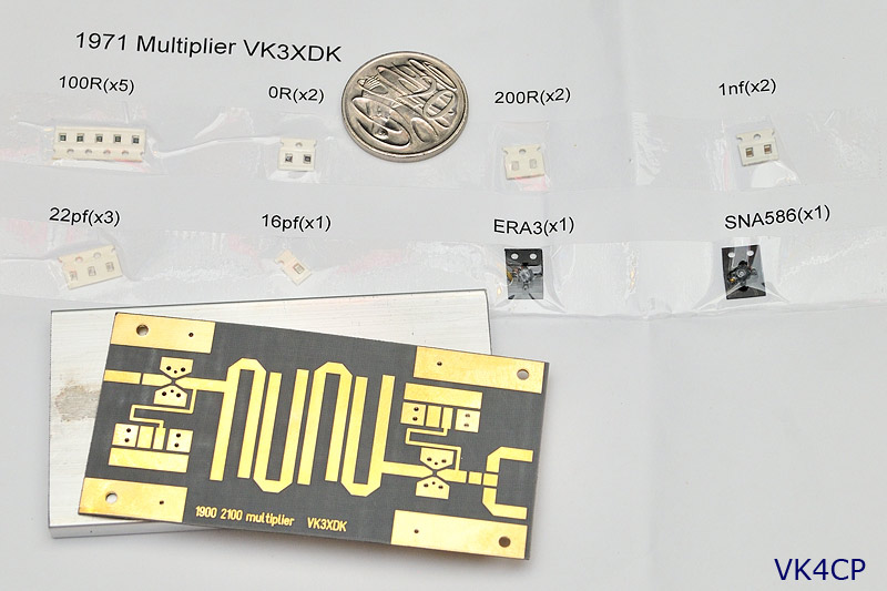
Above: Multiplier kit. On-board parts supplied, along with an aluminium base-plate.
Note that the multiplier kit isn’t used as a multiplier as such.
It takes the 1970 MHz signal from Agile PLL, amplifies it, and provides two outputs.
No documentation was received with this kit (no schematic or overlay), so I have emailed Graham asking about this. I’m sure it’s a simple oversight.
So, the collection of “stuff” so far looks like this, (on-board components to be soldered to the PCBs not in this photo)…

Now, to start assembling these boards. 😀
Whilst you can get away with standard epoxy at 2.4GHz, a 10GHz system will be coming soon after the 2.4G here, and it is definitely better to use the silver epoxy at 10GHz.
So I might as well bite the bullet, get the silver epoxy anyway, and do it right.
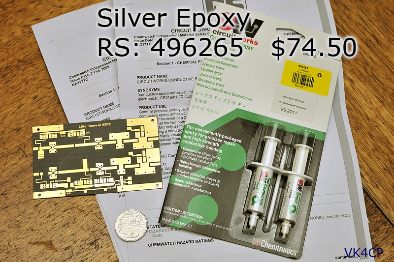
Above: Silver epoxy from RS components. Not cheap, but not prepared to waste a day phoning and driving around all over the place to save a few dollars.
FREE next day delivery on this with RS.
And to bolt the SMAs to the aluminium base plate
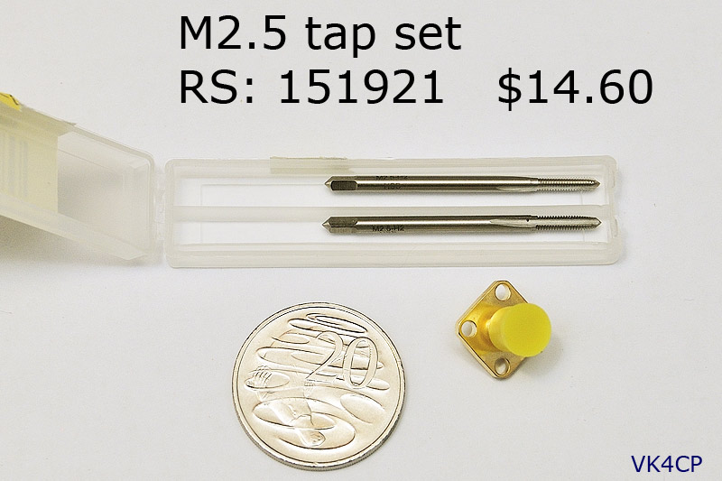
Above: M2.5 tap set from RS.
OK, finally some time to play!
Powered up the ISOTEMP 134-10 10MHz OCXO and the VK3XDK PLL Synthesizer board tonight, both for the first time.
Looking at the OCXO first,
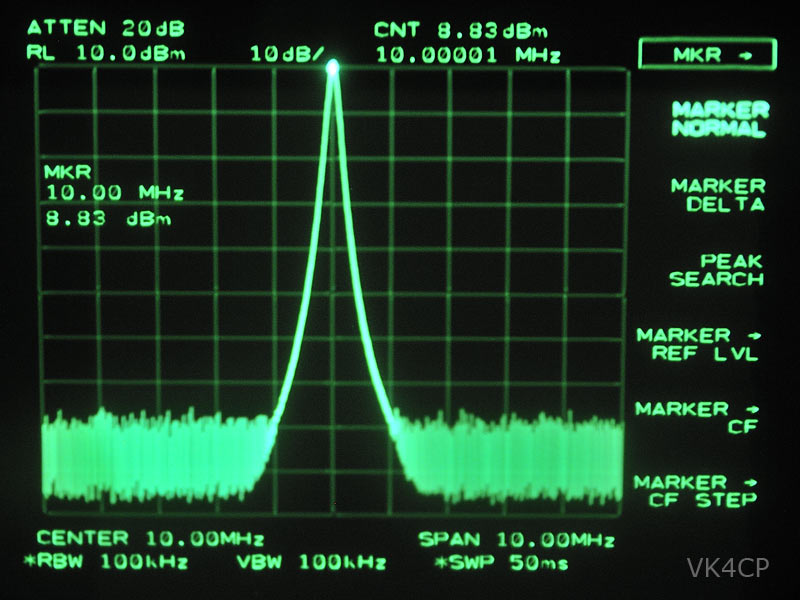
Above: The ISOTEMP 134-10 delivers almost 9dBm into a 50 ohm load, plenty to drive the PLL board.
It maintained this o/p level with supply volts down to 10.3V, so the manufacturer is being conservative in specifying +13VDC +/- 2VDC.
At 4.6V, it delivered 0dBm, and it stopped working altogether at 3.5V.
I discovered the 4-way DIP switch on the synthesizer board was “dicky”! 😯
The least significant bit was not switching, and this was confirmed by a simple multimeter continuity test across that switch.
At first I noticed that the PLL was only generating every 2nd frequency in it’s table, as I was trying out all the combinations.
No problem, as the PLL board only needs to generate one frequency here.
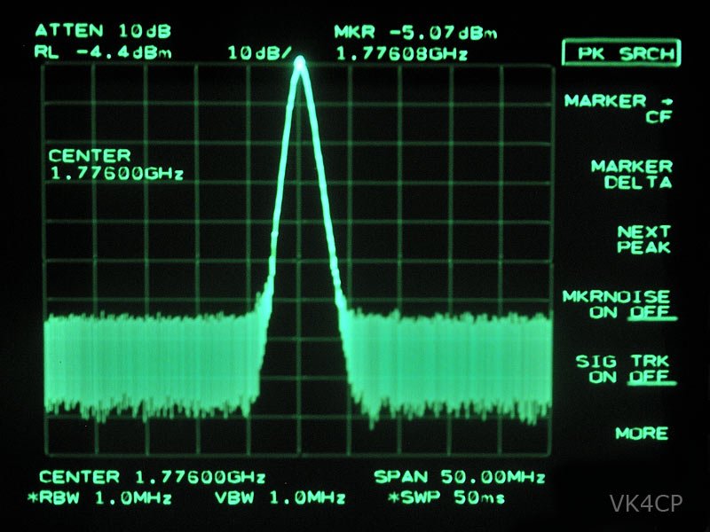
Above: VK3XDK Synthesizer board at 1776MHz output, delivering a nominal -5dBm
The PLL Synthesizer board had a new 4-way DIP switch fitted today.
A 3-way right angle header plug was also fitted to the board to make programming a bit easier.
The pins were cut flush with the PCB, creating a surface mount part, and very easy to solder to the PCB.
(Some superglue was also applied under the plug for extra mounting strength.)
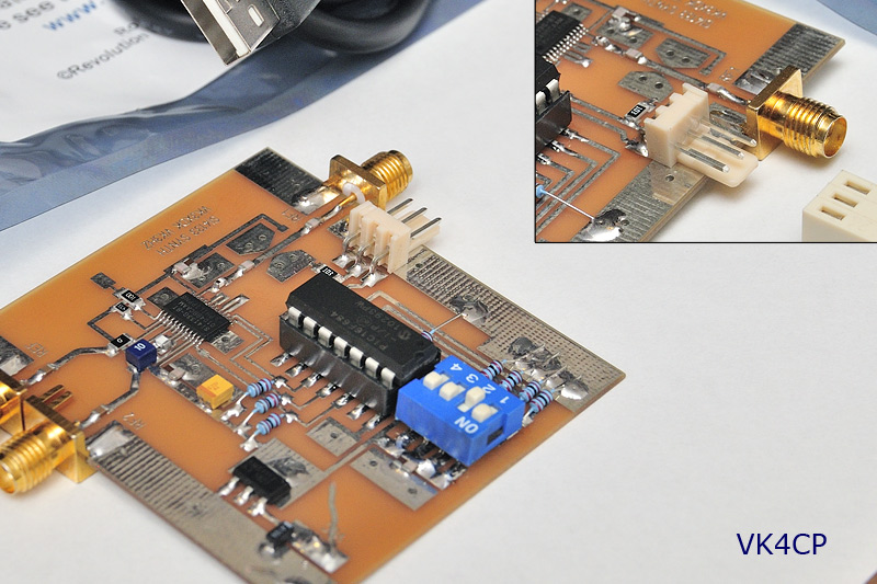
Above: 3-way 0.1″ right/angle header fitted at the programming port. Polarised header makes it hard to connect it arse-about 😉
It’s most unlikely you will have to re-program it once you’ve initially set it up, but this makes it a bit more elegant.
Then a 3-way 0.1″ socket to 3.5mm stereo socket adapter was made to suit the PICAXE USB programming lead.
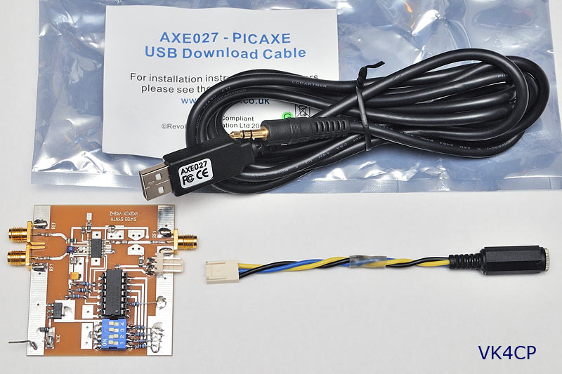
Above: PICAXE AXE027 USB programming leads plugs straight in – no soldering!
For under $3, this makes programming a quick and easy no-soldering exercise.
3-way male header: Jaycar HM3423 $0.35
3-way fem socket: Jaycar HM3403 $0.55
3.5mm stereo line socket: Jaycar PS0134 $1.95 (which you will need anyway)
+ some hookup wire from the junk box
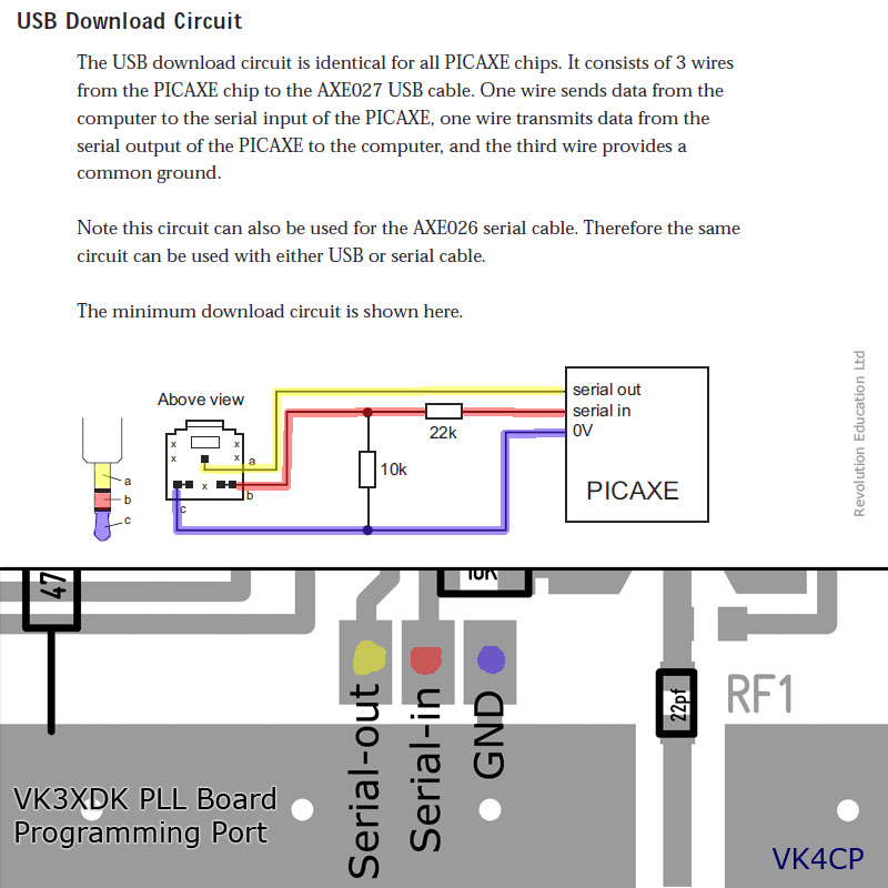
Be aware when wiring up the 3.5mm socket, that the wiring is not what you might expect!
ie, GND does NOT go to the sleeve of the connector, and the PICAXE manual depicts a PCB mount 3.5mm socket.
Here’s a colour-coded diagram I prepared earlier…
The PICAXE [url=http://www.microzed.com.au/index.php?main_page=product_info&cPath=11_29&products_id=62]AXE027 USB programming lead[/url] ($29.95) was ordered from the Australian distributor, [url=http://microzed.com.au/]MicroZed computers[/url], here in Brisbane, (and received the following day!).
Like some USB devices, follow the setup instructions to the letter when installing the USB driver.
It took 10 minutes of mucking around to install (would have taken 2 minutes if I had read the instructions in the first place!).
Programming a PICAXE part is a piece of cake!
Power the PLL board up, connect your programming interface lead, and run the PICAXE editor (FREEware) program.
Open the BAS file, make your edits, and click the progam button to upload the code into the part.
Programming software, and USB cable driver can be downloaded from the [url=http://www.rev-ed.co.uk/picaxe/software.htm]PICAXE website software page[/url].
I went to read the PICAXE part, but I’m not even sure if you can do this with the programmer.
Graham, VK3XDK, sent me the BAS file he supplies as standard anyway, so I simply opened this up with the programmer.
Don’t forget to save it as a new file name, so you keep a copy of the original.
My PLL Synthesizer board has now been re-programmed to give 1970MHz for the LO.
(To make room, I got rid of the 24GHz injection freqs)
The VK3HZ code works a treat! 😀
No need to power down to change frequencies now.
With email received from others, some PLL Boards out there may not be setup to generate 1970MHz as-is.
If your PLL is not locking at 1970MHz, this may involve a tweak to the small printed inductor.
The inductance is reduced by placing a solder short across it.
A lower inductance will raise the center of frequency lock.
(I ordered my PLL Board along with the 2.4GHz transverter kit, so VK3XDK may have added the inductor short specifically to suit operation at 1970MHz.)
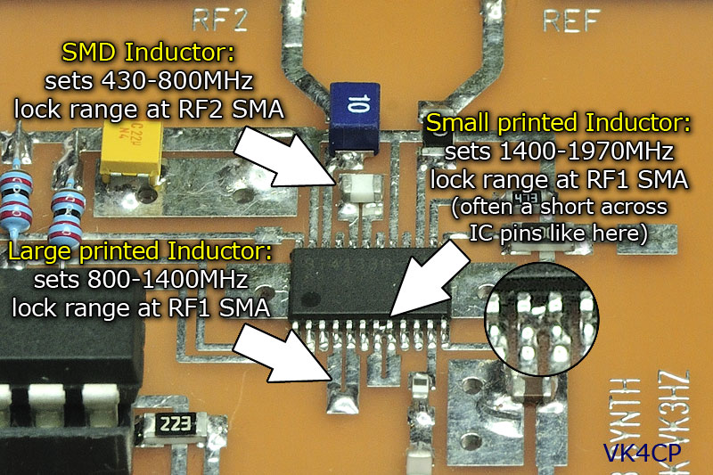
Above: Inductor details. Note solder short across IC pins 7 & 8.
My PLL Board does not lock at the lowest standard frequency of 1008MHz, and I haven’t moved the inductor short to try and obtain this, as it is not required for the 2.4G transverter anyway.
😀
Catching up on a few pictures of recent progress…
Both the 1900-2100 Multiplier and 2.4GHz transverter PCBs were glued down to their respective aluminium base plates using silver epoxy.
Only a thin smear is required, so the silver epoxy kit will do many boards.
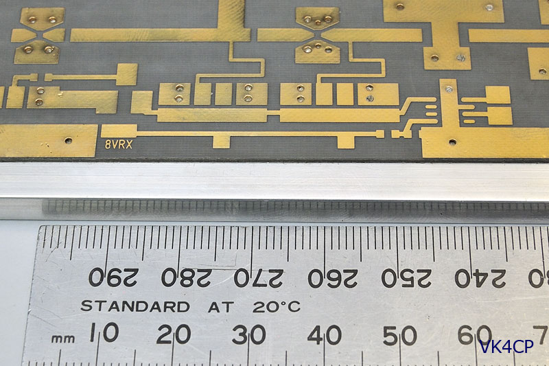
Above: PCBs fixed to base plate using silver epoxy. A nice flat bond is not hard to achieve.
The CW2400 silver epoxy data sheet mentions that better continuity and hardness properties can be achieved if the epoxy is heated up whilst curing (compared to 25° room temp).
This can be done by giving the base plate side a blast with the heatgun all over, and letting it cool naturally.
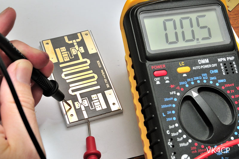
Above: Look Ma! No screws. DC continuity check between PCB top side and base plate.
(BTW, multimeter reads 0.5 ohm when the two probes touch each other directly – time for a new MM battery!)
Isopropyl Alcohol (IPA) cleaner is very effective for cleaning the aluminium base plate in the first place, and any silver epoxy residue away.
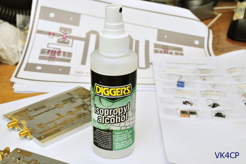
Above: This 100mL IPA spray pack was obtained from Bunnings (about $7), but I later discovered Jaycar also sell IPA in two sizes (and it’s cheaper at Jaycar)
Remember this: It is much easier to mount the SMA connectors before any parts are fitted to the boards.
Instead of using self tappers, yuk, I used 2.5mm screws to mount the connectors to the base plate.
Position the connector, mark only one hole for now, then in a drill press, drill a 2mm hole, then tap it with the M2.5 tap.
(Do not attempt to use a hand drill with small drill bits – that will end in tears!)
Mount the connector with this first screw, then drill through the middle of other connector hole (in situ) to ensure an accurate second hole alignment.
(There is very little wiggle room when using M2.5 hardware)
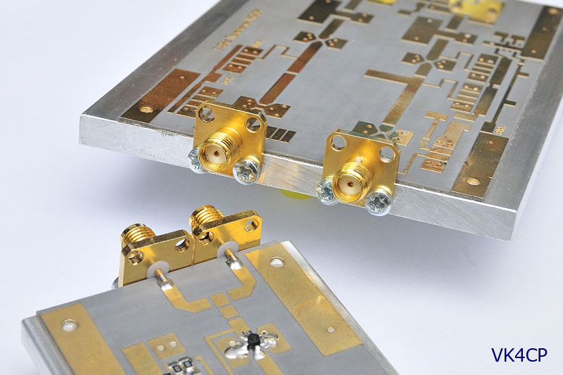
Above: SMA connectors fixed to base plates with 2.5mm screws in tapped holes.
Don’t forget to use some “soft jaws” on the PCB side of the drill vice.
Ok, I have this running on the shack bench now!
Here’s a quick look at the beast. Shack is a mess, like a bomb went off, so no wide shots. 😉
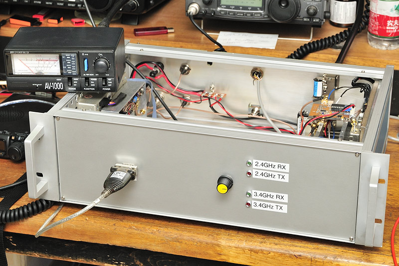
Above: Front view. At left, RS232 port from Thunderbolt going to laptop. Band select on right, with LED indicators for mode.
Fitting an LCD display, where the DB9 connector is, will ultimately replace the need for an external laptop to interogate the Thunderbolt status.
Above: Looking into rear corner. Thunderbolt, DC input wiring and fuse, along with GPS antenna BNC, and 2 (of 4) 10MHz O/P BNCs.
At right you can see the ANT port for the [future] 3.4GHz system, along with the control cable (a CB 4-pin microphone plug/socket) coming from the 817.
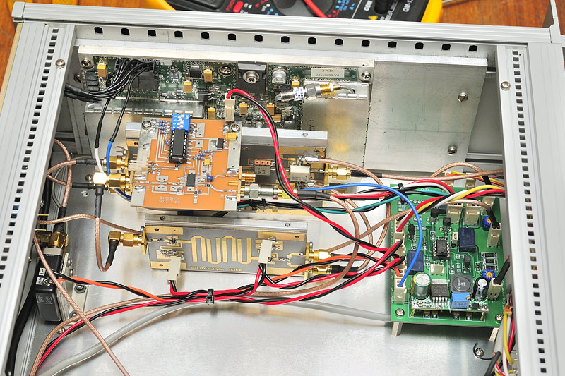
Above: Looking to right. VK3XDK 1900-2100 multipler board in front, with 2.4G transverter board behind that, and a Spectrian 30W PA mounted on the enclosure side.
In addition to the Spectrian base plate, I have mounted the Spectrian onto another 6mm aluminium plate for extra heatsinking capability.
VK3XDK PLL board bolted on top of transverter board, sitting horizontal.
VK4CP Sequencer board at front.
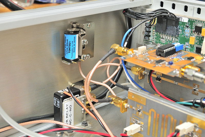
Above: Looking to rear panel. Tohtsu coax relay from FT817 for input switching between 2.4G system and [future] 3.4G system.
Output SMA relay for T/R switching between XDK transverter RX path and the Spectrian amp O/P.
All the coax is RG-316 teflon, which is very easy to work with.
At 2.4Ghz and lower, the short runs of coax mean any loss is insignificant. There is no need for hardline or semi-rigid cable.
(The only hardline used is the 086 stuff that came with the Spectrian PA, which is terminated with SMA connectors)
With the FT-817 set to medium power (2.5W out), I get +2.5dBm out of my sequencer, going into the transverter TX IF i/p
Coming out of the VK3XDK 2.4G transverter board is +21dBm – exactly on spec. 😀
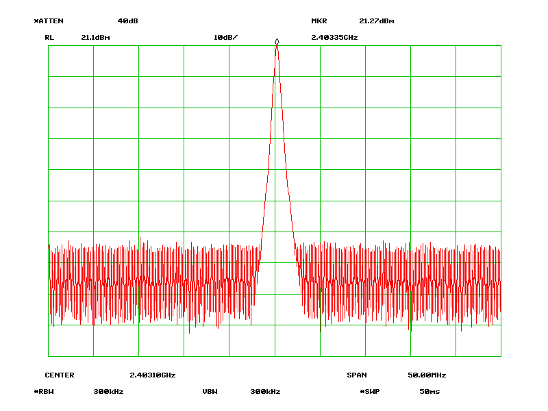
Listening to myself on the IC-R1500 directly on 2403.100MHz FM, it sounds nice and clean.
VK4APN wrote
Where did you obtain the 150 ohm smd 1 watt(?) resistors?
These resistors were sourced from RS.
In fact, I purchased quite a bit of stuff from RS.
Their online ordering, and free delivery make it so easy… so I couldn’t be bothered with Rockby etc.
Quite happy with the Spectrian power amplifier too. 😀
Exactly as PyroJoe says in his eBay listing, 35dB of gain can be expected with these 30W boards.
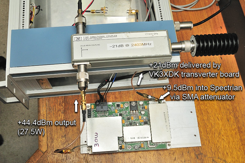
Above: Spectrian temporarily removed from transverter enclosure for test.
The VK3XDK 2.4GHz transverter board is delivering +21dBm out.
I feed this via an SMA attenuator (nominally 12dB) and +9.57dBm is being fed into the Spectrian PA.
The Spectrian saturates at any more than +10dBm in, so there is little to be gained exceeding that drive level.
As I cannot read above +30dBm directly with the spec an, I use a HP 779D Directional Coupler (obtained off eBay).
The coupling port was measured being -21.0dB at 2.4GHz.
The coupler’s through port was terminated with a Weinschel DC-8.5GHz 50W termination (another goodie picked up from eBay).
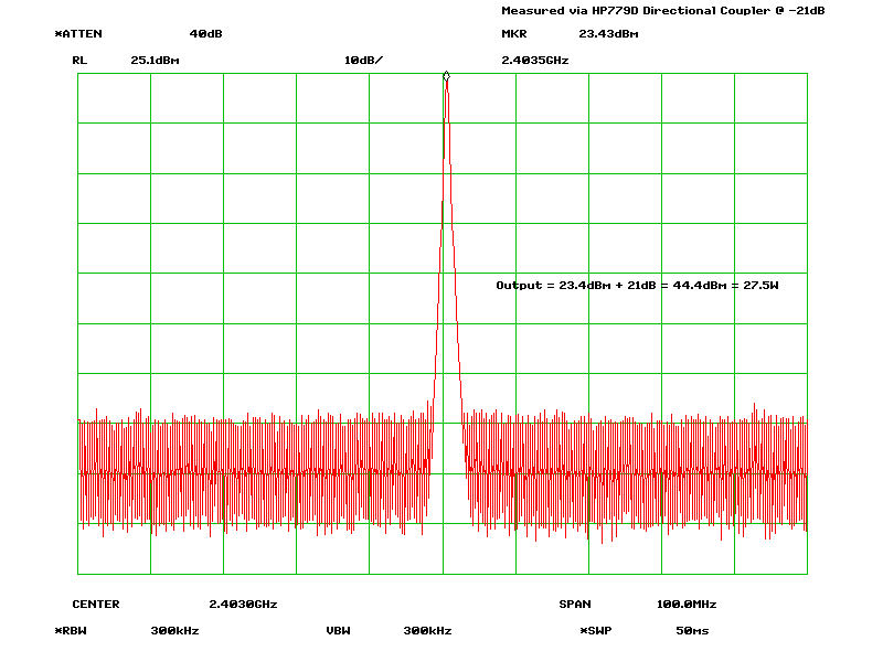
Output is 23.4dBm as measured + 21dB via coupling port = +44.4dBm being delivered out of the Spectrian.
This translates to 27.5W, so happy with that.
At 13.8V, this Class-A amp draws around 10A delivering this output.
These Spectrian boards are not known for their efficiency, but who cares, they are plug and play, and work as advertised.
They are a relatively cheap and easy way to generate some grunt on 13cm.
Quiescent current is just under 1A in idle.
I’m glad I bolted the Spectrian base onto another (larger) 6mm aluminium plate.
It’s quite hot, but all my testing has been with FM, and I don’t expect heat to ever be an issue with the low SSB (or CW) TX duty cycle in Field Day use.
Incidentally, the second harmonic at 4.8GHz sits at -11dBm (80uW).
This article is not yet finished – please come back later
