This v2.3 firmware fix addresses the date translation error which became apparent on January 1, 2020.
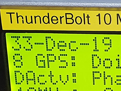
Due to unforeseen coding bugs in the WNRO (Week Number Roll Over) fix released in 2017, 01-Jan-20 was incorrectly displayed as 32-Dec-19. The day after the 31st.
02-Jan-20 was displayed as 33-Dec-19, and so on.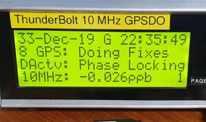
In addition to fixing this bug, leap year detection has been made fool-proof and date calculation has been extended to the end of 2032. Basically, as much as I can squeeze into the remaining memory slot.
Date simulation was performed, generally the first week in March, for each and every year up to 2032, I am 99% confident this fix should be the last required.
Seeing the year “32” looks a bit weird and why am I thinking of Sci Fi shows?
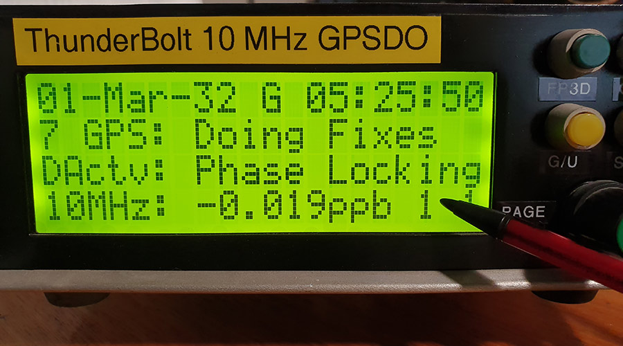
Above: Pointing to a leap year check byte. 2032 is a leap year. This check byte was removed after testing was completed.
The only real way to check date calculations is with a time consuming process of hard-coding a GPS week number which overrides the Thunderbolt’s reported week number (which requires a WNRO correction anyway), then and cross-checking the display with an online GPS calendar.
The photo above was taken at this point in the week (Monday afternoon, GPS week # 2087), but hard-coded as GPS week # 2721.
This correlates with the GPS calendar calculator.
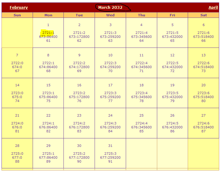
This date correlation check was performed for each calendar year from 2020 to 2032.
How the display with v2.3 looks now:
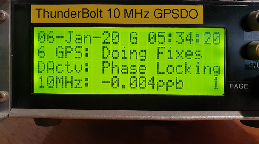
Above: this photo was taken Monday 06-Jan-20 at 15:34:20 local (UTC +10)
Alternative versions
In addition to the version described above, I offer two alternative versions;
v2.3ND (no date)
Perhaps you look at your watch or phone for the date, and don’t want the date on the display to begin with.

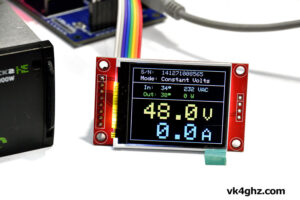
Above: v2.3ND reinforces the time mode, UTC vs GPS time.
v2.3RM (receiver mode)
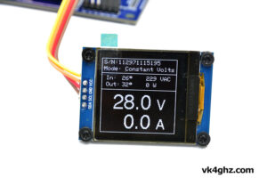
Instead of the date, this version displays an abbreviated form of receiver mode on page 1.
On page 2 (which displays the receiver mode anyway), only the time appears on the 1st line.
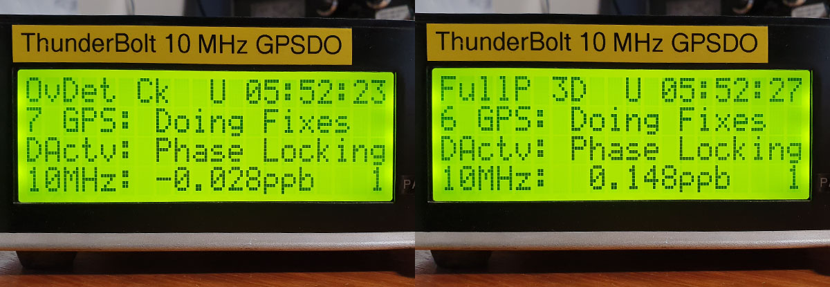
Above: v2.3RM displays receiver mode, eg; Over Determined Clock vs Full Position 3D
If… if, there are any unforeseen issues that should affect the date calculation in the future, then these alternate versions can be considered as future proof fall-backs.
I personally think seeing receiver mode right there on page 1 along with disciplining activity and the 10 MHz PPB count is most useful.
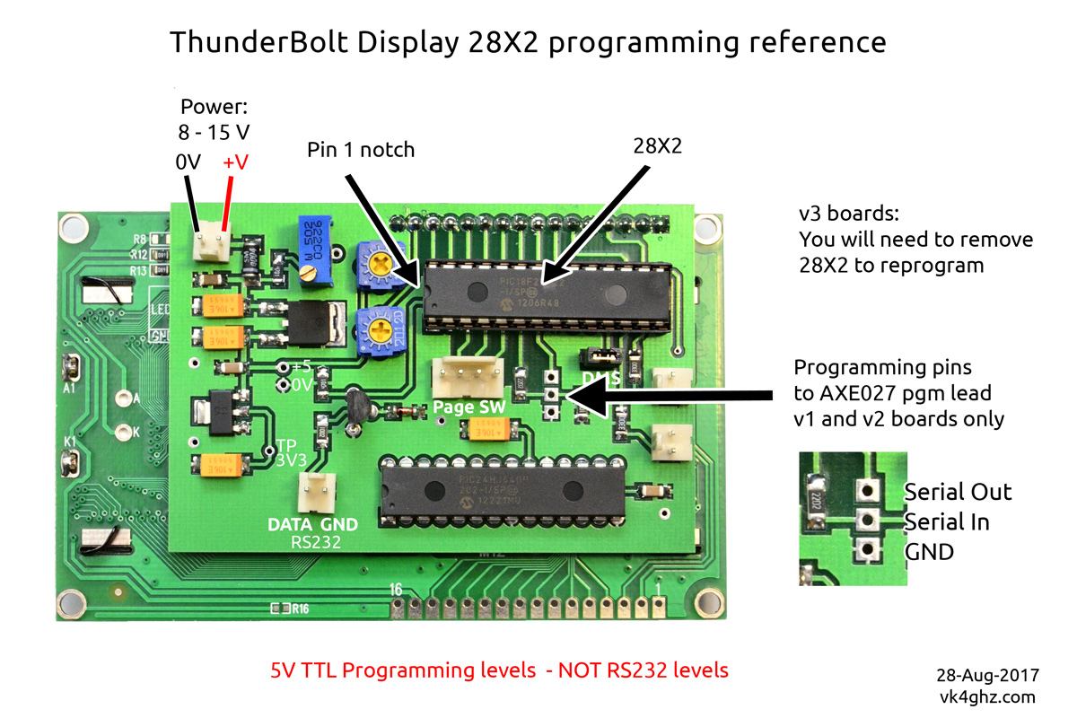
Thunderbolt display micro-controller
The microcontroller on the Display board is a PICAXE 28X2, this is the chip in the 28-pin IC socket.
The other chip soldered to the PCB is a math co-processor – and does not need to be touched.
You will need the following
• PICAXE AXE027 USB programming lead (or direct equivalent)
• PICAXE Editor program http://www.picaxe.com/Software/PICAXE/PICAXE-Editor-6/
• You may need a breadboard, 22k resistor, 10k resistor, and 5V supply to make a temporary PICAXE programming jig
Understand that I cannot answer random questions about other programming leads – use a proper AXE027 if in doubt.
For answers about using the PICAXE Editor – refer to the PICAXE website for FAQs etc
Re-programming the Display micro-controller
If you have a v1 (2011) or v2 (2012) display board, you have two options to program the 28X2;
1) on-board, there are programming pads you can temporarily solder to.
2) off-board, in a breadboard etc
v3 (2013) boards do not have these programming pads, so you will need to remove the 28X2 and program it off-board.
Assess whether you should remove your Display board from its enclosure to properly access the programming pads or removing the PICAXE without the risk of bending or causing fatigue to the pins.
Programming on-board
• display board needs to be powered up whilst programming.
• connect up PICAXE programming lead (AXE027) or equivalent
• using PICAXE Editor, program slot 0 and slot 1 (order is not important)
• remove programming lead
Programming off-board
• disconnect power to Thunderbolt
• NOTE ORIENTATION of the PICAXE 28X2
• carefully remove 28X2
• insert 28X2 into your breadboard programming jig
• connect up PICAXE programming lead (AXE027) or equivalent
• using PICAXE Editor, program slot 0 and slot 1 (order is not important)
• re-insert the 28X2 into your Display board, noting orientation
To display the Thunderbolt’s internal firmware version, the Thunderbolt, Commander and Display need to power up together.
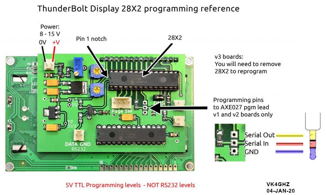
V1 and V2 programming interface:
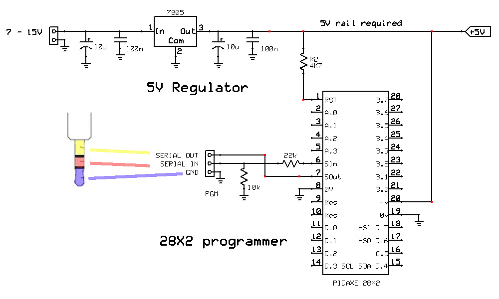
V3 – suggested circuit for off-board programming:
If you cannot set a PSU to 5.0V, use a standard 7805 type regulator circuit to generate a 5V rail
10k and 22k programming interface resistors must be used.
A small breadboard is ideal for knocking up this circuit on.
![]() PICAXE .bas File Downloads:
PICAXE .bas File Downloads:
You will need to program both corresponding slots, slot 0 and slot 1 for your chosen version.
Do not be concerned with the slot numbers, as they are hard-coded into the code – just program both files as they are.
Programming order (slot 0 vs slot 1) does not matter.
v2.3 (displays corrected date until end of 2032)
v2.3ND (no date)
v2.3RM (receiver mode)
Thunderbolt Display, 28X2 slots 2 and 3
Slots 2 & 3 were not updated, so these are still current versions
Thunderbolt Display Slot 2 v2.2
Thunderbolt Display Slot 3 v2.2
Thunderbolt Commander