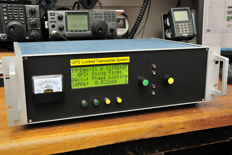
Unit #1 – Within Transverter enclosure, no screws visible from front panel
This is the part I have been dreading… actually mounting the display, and preferable in a strong manner that is invisible from the front.
To be really strong and survive MAD (Microwave Activity Day) use tends to rule glue out.
To be invisible means no screws through the front panel, although this is the quickest and easiest method. 😉
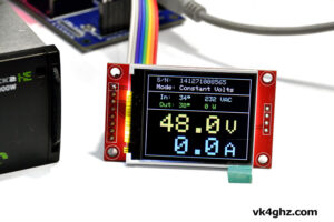
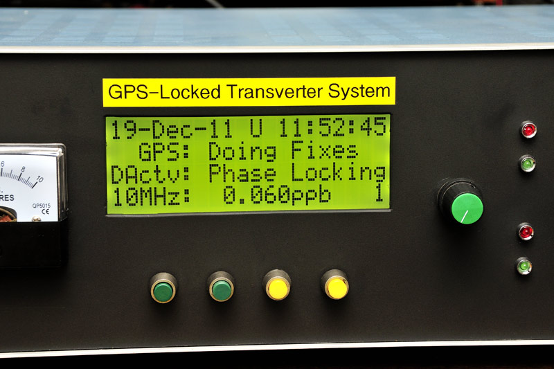
Let’s have a look at the final result, and then we will step through how I got there. Note that this relates to the Jumbo sized unit.

Only common handyman hand tools, and a drill press here, nothing fancy at all.
The actual rectangular cutout was started by drilling holes in the corners, so that a jigsaw could then be used. (I also tried the reciprocal saw, which gave a much straighter cut, having a wider blade than the jigsaw). Then, there was lots and lots of filing.
The lines are not perfect, but good enough.
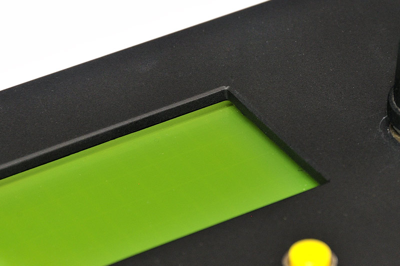
A small bevel was filed in around the LCD cutout:
I’ve collected aluminium brackets and things, generally ratted out of old equipment, over the years. You never know, it may come in handy, some day, right?
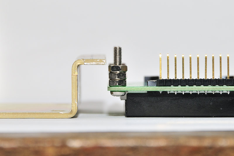
These look interesting, (can’t remember what it come out of), and have a very useful profile: (You could fabricate something similar with two pieces of “L” bracket, screwed together, facing opposite ways.)
And three M3 nuts make the perfect spacer. Do you see where this is going?
The display used here was one that was destroyed during project development. Opps. Never allow your +5V rail to short with 13.8V. LCDs don’t like 13.8V, but do become good paperweights. 😳
Now we can mount, flush with the front panel, from behind. We just need some existing holes, either side of the display, where the brackets can be held in place with other switches and things passing through the front panel.
Well, one of them is going to be the display’s own page select switch. And in this case, a DC Ammeter, is on the other side of the display. Perfect!
From the front, align the display, and mark up where the holes are, and anything that needs a cutout. (In this case, the outline of the meter)
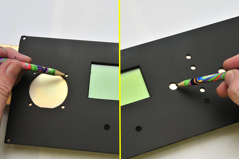
Remove front panel out of the away, and check where we need to drill and cut, so that it will fit in from behind.
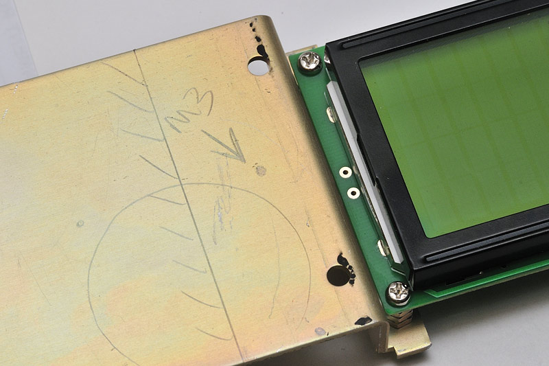
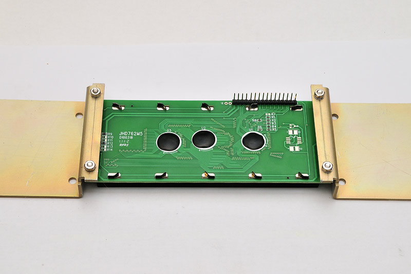
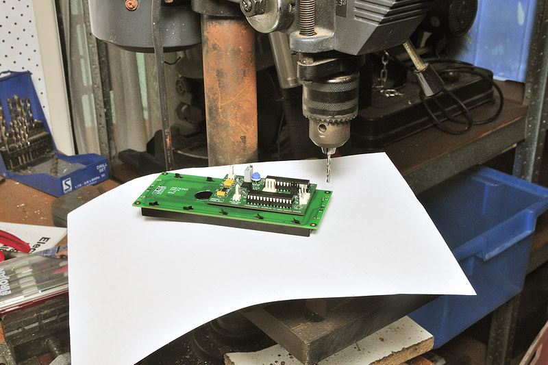
By the way, the Jumbo LCD has M2.5 mounting holes. If you have M2.5 bolts, washers, and screws, no problem. I use M3 instead, so the mounting holes had to be drilled out.
Be careful, as the fibreglass PCB is a soft material, the drill bit will tend to “grab”. Just be careful, and hold the display down flat firmly.
To prevent scratching the glass and bezel, I laid a piece of paper down:
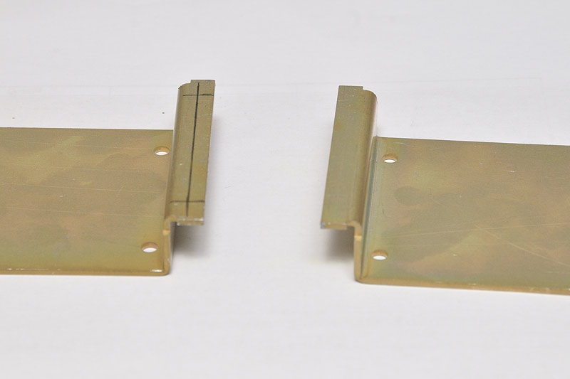
Fast forward, and our two brackets have been drilled and cut to suit:
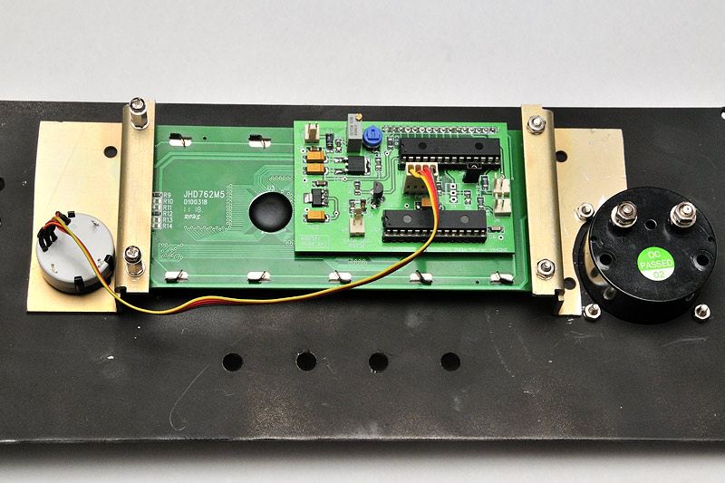
A closer view of each side:

Back in the shack, and wiring it up:
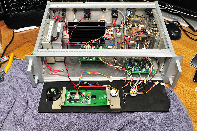
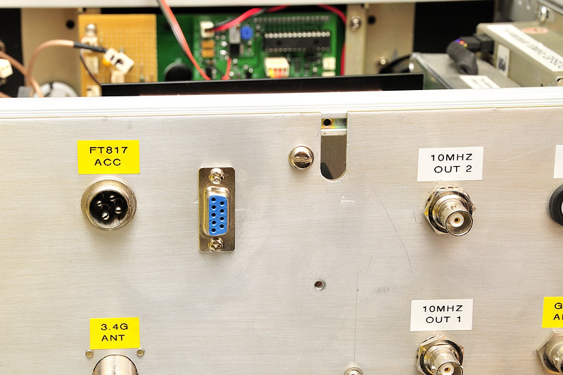
The DB9 serial port, that was originally on the front panel, has now been relocated to the rear panel… just in case we ever want to connect the PC/laptop up to the ThunderBolt.
During all that cutting, filing, and drilling, the front got a bit scratched, despite trying to be very careful. Black paint hides a lot sins!

You should be able to mount a standard sized display in a similar way.
There’s bound to be many others ways of achieving the same end result. Post up some pictures of what YOU did, for others to see!
Unit #2 – In-shack use only – Inside a plastic enclosure
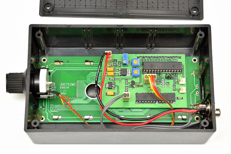
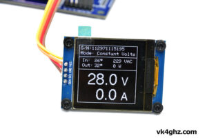
Nothing fancy about this! Inside a UB1 Jiffy Box Jaycar HB6011 $4.45) It’s a nice tight comfortable fit.
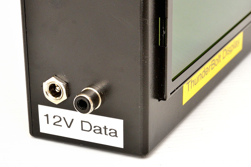
Added a DC coaxial connector for +12V, and an RCA for RS232 data at one end. Page selection switch on the other end.
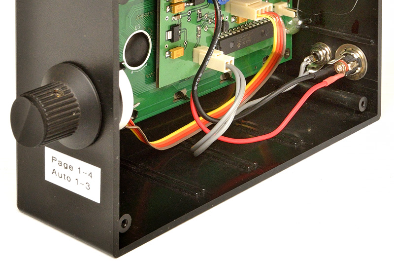

For in-shack use only, so hot melt glue holds the LCD module in position at both ends. (Recommend you bolt the LCD to the enclosure, if you are taking it out and about in the field though)
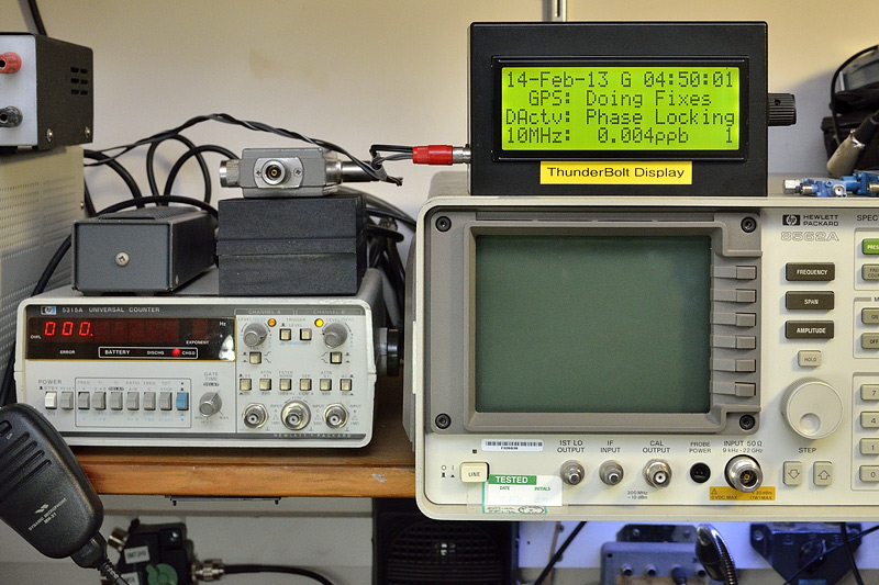
… and plonked where it needs to be! Near the test equipment that uses an external 10 MHz reference.
Mounting a ThunderBolt Display by VK3YFL
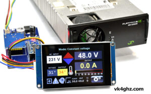
Here’s my mounting implementation of Adam’s ThunderBolt Display. It’s in a similar enclosure that I used for just the ThunderBolt, but a little larger to allow incorporation of Adam’s Display (Jaycar HB5446). I hope I’ve still room for the Commander, which seems a necessary addition.
UPDATE: There was room and the Commander has now been added and the second photo shows the addition of the switches on the rear.
Mounting a ThunderBolt Display by VK2GOM
I was one of the first to receive the Thunderbolt Display from Adam, and was very impressed with the design, build, and the obvious hours that had gone into the coding and testing.
I tested it on the bench initially, and everything worked great. I decided to box mine up as a standalone / portable unit that I can move around my Thunderbolts. I use some Thunderbolts /P and have another plumbed into the shack as a 10MHz reference for the test gear, and to reference lock my HF radio.
Hardware was obtained from Jaycar.
I thought the box was initially going to be too big, but it worked out fairly well. I mounted everything on the lid. I drew up all the holes and cutouts in CAD to get everything spaced properly, printed it on sticky paper, stuck it onto the lid then off to the garage and the drill press and an hour or so later I had the front panel done.
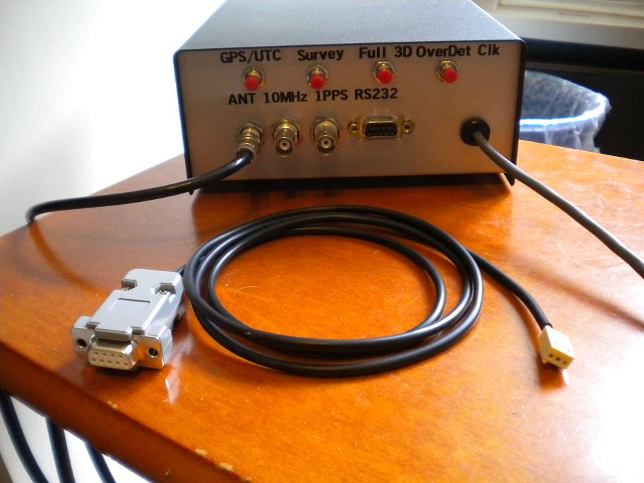
The push switches are for the Thunderbolt Commander which will be integrated into the box. The knob on the right is the Thunderbolt Display page selector. The LED bezels will house the Critical and Minor alarm LED’s (another trip to Jaycar). Unfortunately they have run out of 2w headers and I am loathe to solder to the Thunderbolt display board.
I have also yet to install a clamp grommet that will have a flying lead on it to connect to the Thunderbolt. I thought about a separate plug-in lead, but it’s just another lead to misplace. Attached to the unit, I can’t lose it.
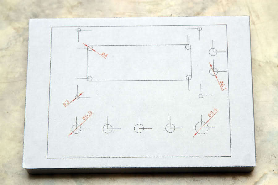
The CAD design of where to drill/cut stuck onto the box lid
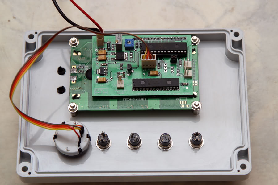
Everything now mounted on the front panel

The front panel so far. The gold connector is a Phono socket for the Volts in / Battery sampling
Now finished with a built-in Thunderbolt Commander so I can use it /P with my microwave gear.
Programming the PIC was a bit problematic, getting the drivers for the programming cable to work in 64bit Windows 7. Got there in the end.
Here’s a picture of it under test on the shack bench with the rest of the gear. Could do with a tidy-up now 😆

73 – Rob VK2GOM / G0MOH
Mounting a ThunderBolt Display by VK3ALB
I’m probably a little different from most Trimble users as I won’t be taking my system out in the field.
I use it exclusively as a time and frequency reference in the shack. I’ve had it for a couple of years and it’s been lying on the bench behind the test equipment cabled together but not in an enclosure. Adam’s display gave me the incentive to complete the project.
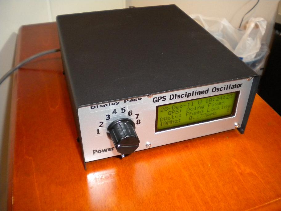
I installed the whole lot in one of those swish Jaycar instrument cases. I’m only interested in the time and making sure the 10MHz is being disciplined so I decided not to install the rotary switch and instead made a little jumper plug to select display mode 6. This means the display always sits on page 1 unless there is an alarm condition. I looked all over for a suitable bezel but no luck. There is a molded 20×4 LCD bezel available overseas but it’s very expensive and very bulky – not what I wanted. So I took the easy way out with the display mount and cut a hole in the front panel. The standard length 3mm screws from Jaycar are just long enough to go through the front panel of the case and secure the display.

This image shows the Trimble in action locking a signal generator and a frequency counter. I installed an 8 way 10MHz splitter in the case which gives me enough outputs to lock everything on the workbench.
Thanks Adam, an excellent addition to the shack.
Mounting a ThunderBolt Display by N1JR
I thought I would post a few photos of my version of Adam’s Thunderbolt Display and Commander.
I built the Display and Commander, along with a Mean Well RS-50B power supply and the Thunderbolt, into a LMB Heeger EAS-500 (6.15×8.5×3.09″) case which is a “clam shell” design where the top and bottom are identical halves which mate.

The ThunderBolt, display and Commander fit in the bottom section, while the Mean Well is bolted to the top along with the pushbutton switches for the Commander on the back panel.


I’ve attached a few iPhone photos of the assembly.
Works great.
When the leap second issue is reset, I expect the minor alarm LED to finally go dark!
73, Jim Robbins, N1JR
Mounting a ThunderBolt Display by HG5ED
Please see my TB display.

ps. the front panel lettering is coming… the cosmetic items…..