Kuhne provide a PLL Lock status LED on the PLL board of their G3 transverter modules.
This LED is inside the module, which is great when the lids are off on the shack bench, but of limited value when out in a real operational environment.
It’s very easy to add an external PLL Lock LED, and position this on the front panel of your transverter to provide confidence that your G3 module has in fact locked to the External 10 MHz reference, rather than just assuming it has.
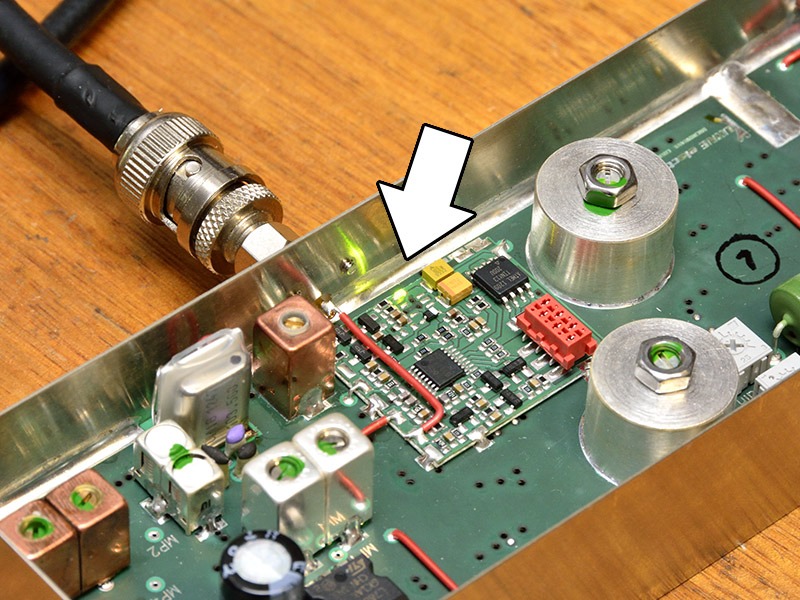
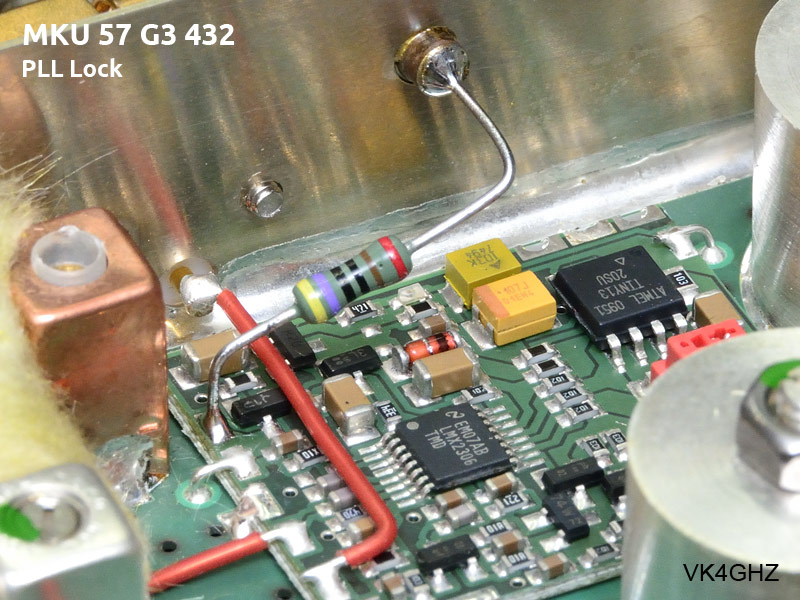
Bringing this signal to the outside world is straightforward using a 1nF feed through capacitor, mounted into the side wall of the G3 module, just near the Ext 10 MHz signal input.
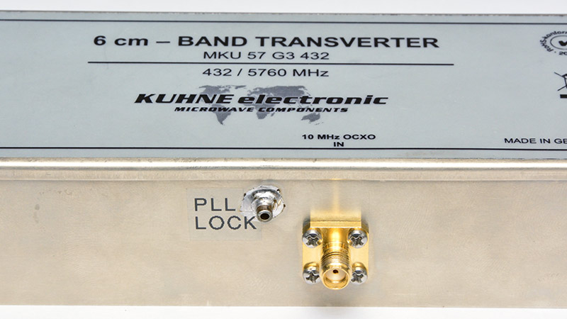
The FT2200 feed through capacitor came from MiniKits, and a 4mm hole is required to mount these. The “German tin box” makes it very easy to solder the feed through to. Drill the hole, and tin around the hole before soldering in position.
It is recommended you do NOT use a hand drill to drill the hole in the side of your Kuhne module. Spend a few moments disconnecting your module completely, and use a drill press. This helps limits the drill bit’s travel, and avoid an “oh shit!” moment. 😉
Remember to allow for the lip of the lid. My holes are located 9mm below the edge.
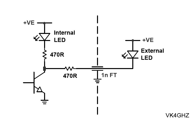
The internal PLL “Lock” LED is driven by an open-collector transistor arrangement, via a 470 ohm resistor. We simply tap off this point for the external LED.
Kuhne thoughtfully provides a pad on the PCB, to access this open collector point.
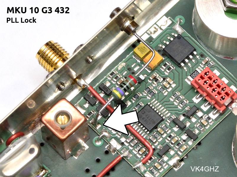
Be aware – PLL boards do vary from model to model.
Note: I only have the 5.7 and 10 GHz G3 variants, and only documents these. You will need to investigate any other modules yourself. This is easy to do using a simple voltmeter, whilst observing the internal LED.
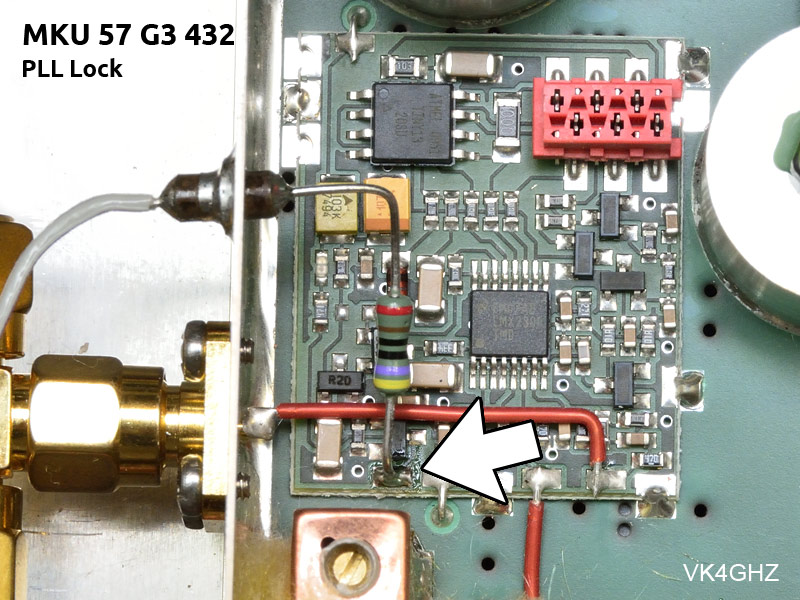
It is convenient to mount a standard 0.6W through-hole type 470 ohm resistor between the feed through and PCB pad.
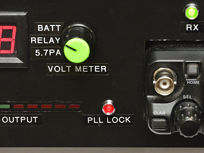
The external “PLL Lock” LED is mounted on the front panel of a transverter system. The anode (A) of the LED is wired to +12V and the cathode (K) is wired to the feed through capacitor. It doesn’t get any easier than this!
Because of the open collector arrangement and 470 ohm resistors fitted inside each module, we can parallel more than one output to drive a common LED.
In my particular installation, this “PLL Lock” LED has been fitted to a dual-band 5.7-10 GHz transverter system. The one LED indicates the PLL Lock status of either band.
This provides operators with an easy visual reassurance of a “locked” or “not-locked” situation.
🙂