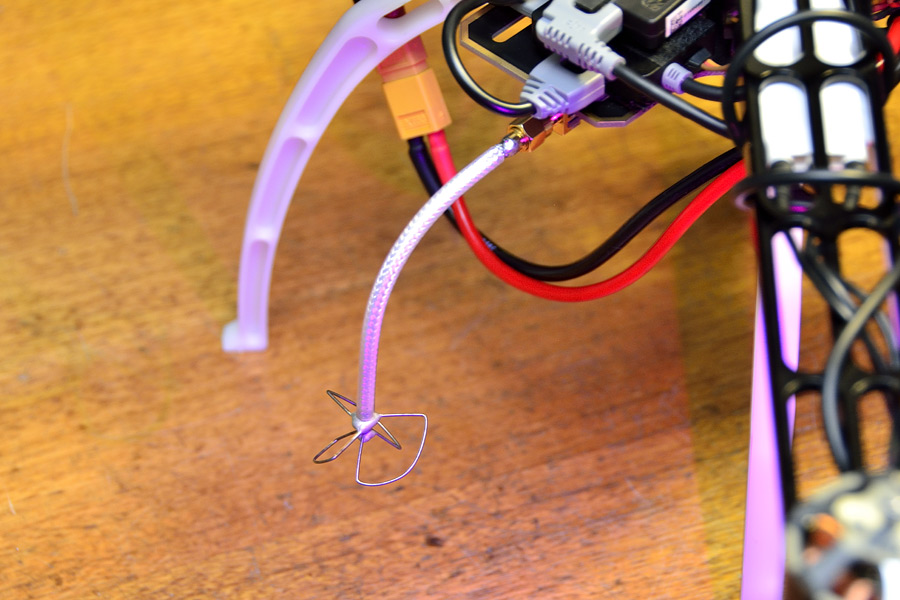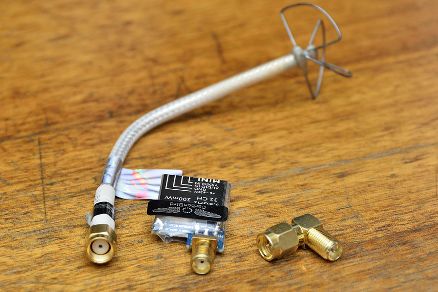
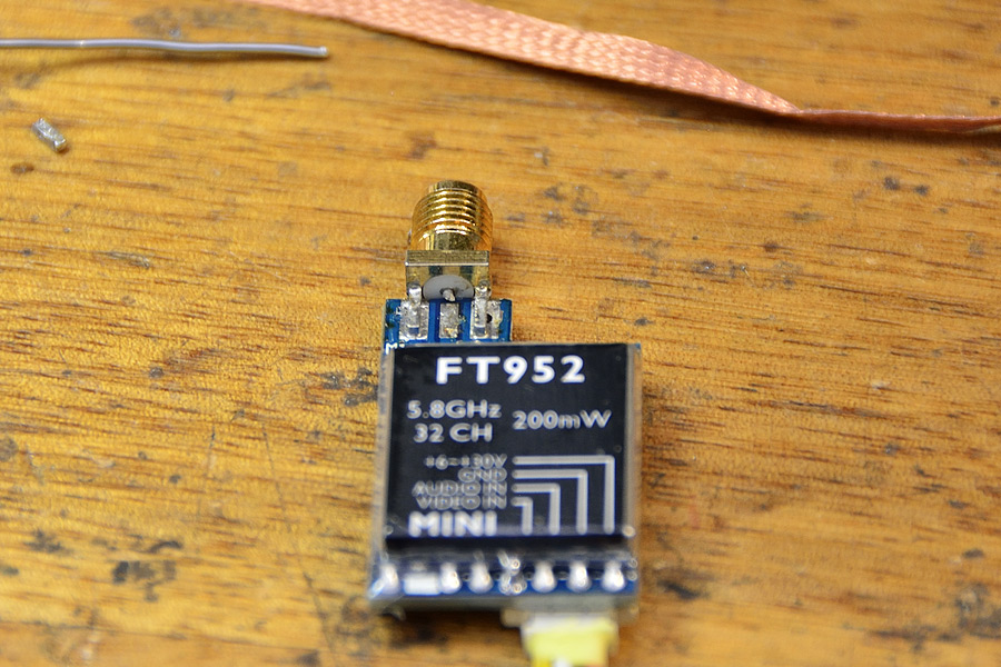
What’s wrong with this picture?

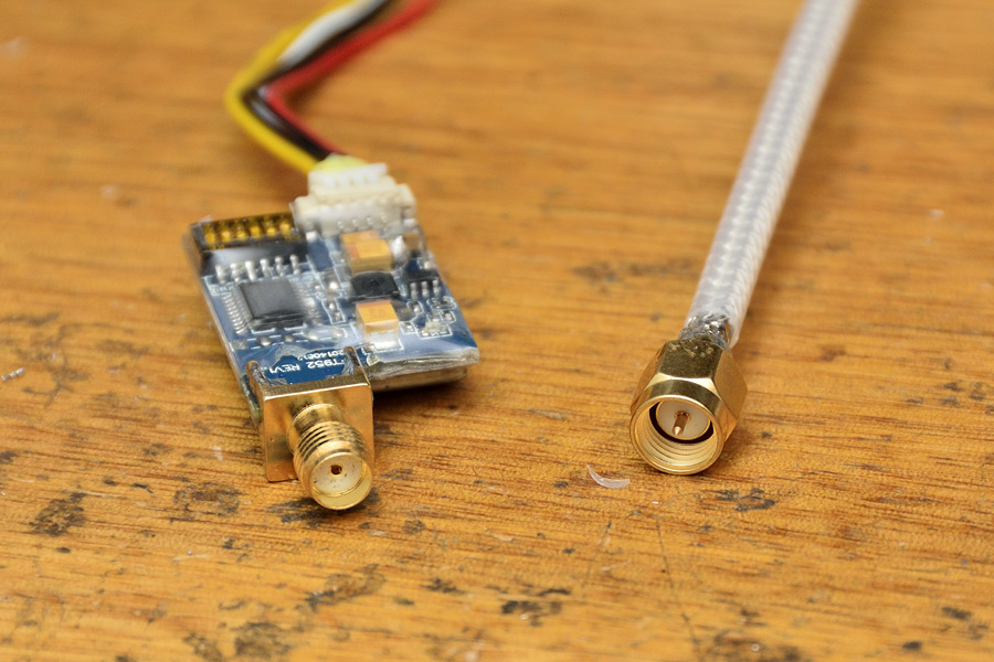
Stupidly, a cloverleaf antenna with a reverse SMA connector (SMA-RP) is supplied with a transmitter than has a “normal” SMA (f) jack, thus requiring an adapter.
These adapters can be relatively lossy at 5.8 GHz, and the semi-rigid coax feedline can be bent and maintain a 90° angle anyway.
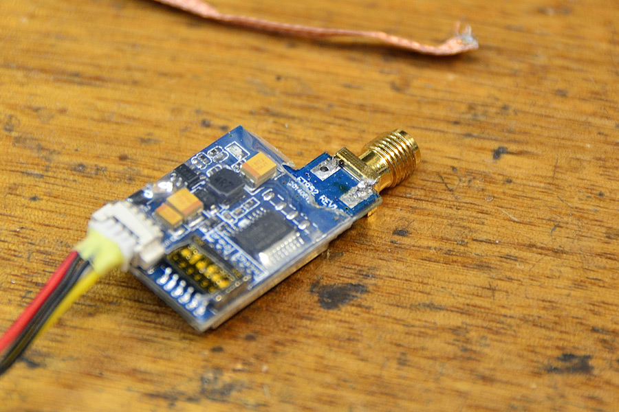
At this point, a problem was noticed with the Carbonbird branded 200mW 5.8 GHz video transmitter, and the extremely poor quality SMA (f) jack that was fitted.
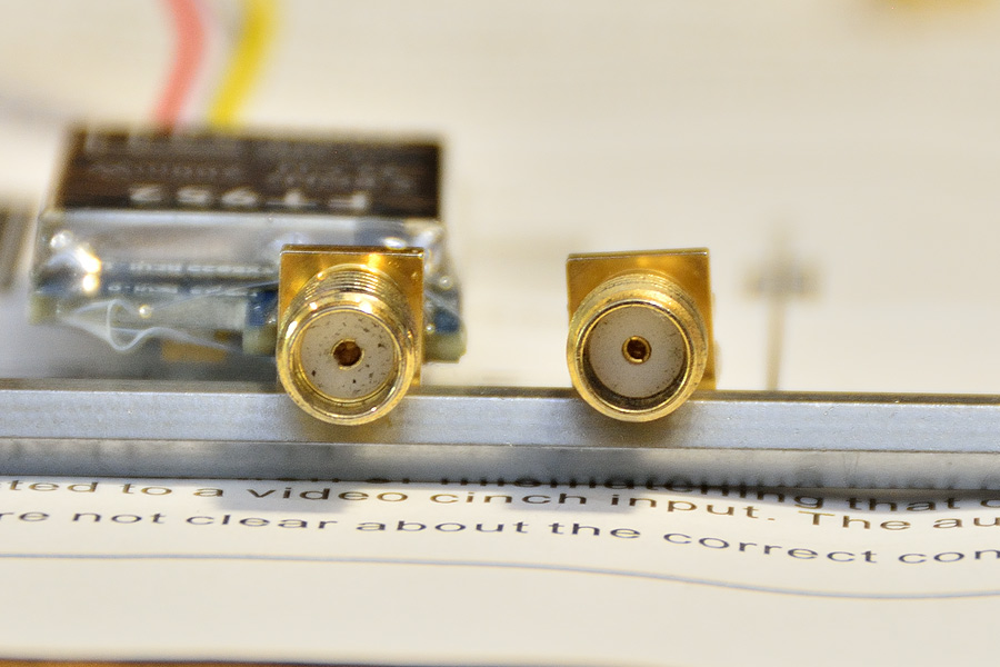
I have never seen an SMA jack like this, where the male pin is such a loose sloppy fit, to the point where the pin itself droops down, as seen in the following picture (you can even see the gap at the top of the pin).
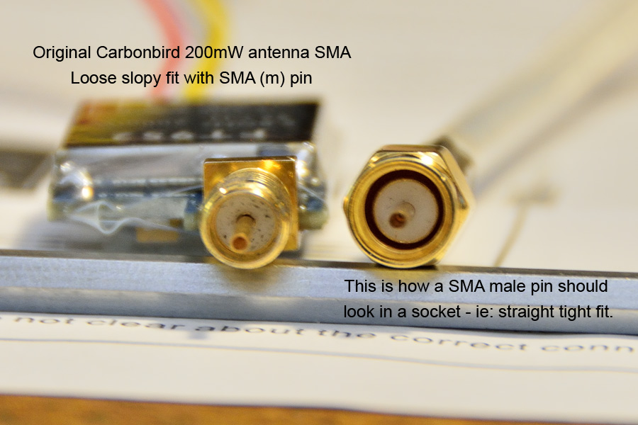
The loose and sloppy female contact can be seen here (left) alongside a better quality SMA (f) jack, on the right.
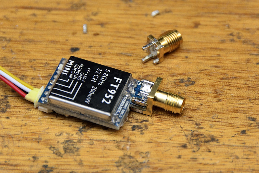
Not wanting to risk an open circuit with the antenna and smoke the transmitter’s final stage, the jack on the Carbonbird TX must be replaced.
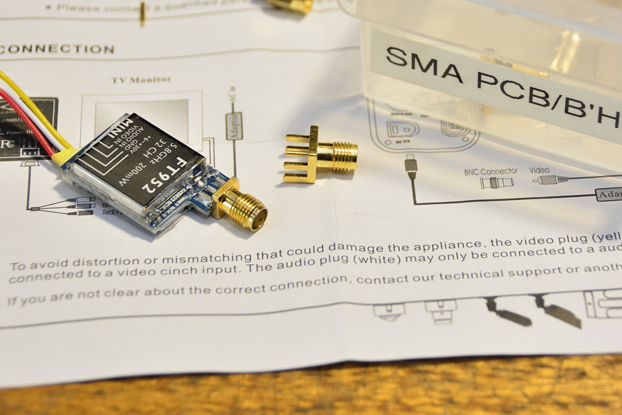
Removing PCB edge launch style SMA connectors can be a challenge, when you want to avoid damaging the PCB at all.
From previous experience, I have found the following procedure works well.
• Using solderwick and a suitable tip, wick up as much solder as possible on the “other” side.
• Using small pliers, bend and fatigue each earth pin off
• Be careful – do not pull copper traces
• Flip the board over
• De-solder the centre pin, and cut off
You can fatigue and bend the top earth pins, but simply heating both pins, and the connector should fall off by itself.
Some PCB edge mount SMA jacks have earth pins with a wider pitch, so in this case, PCB solder mask was scraped away so that the earth pins could be soldered to the copper. Use a Stanley knife blade.

New SMA (f) jack fitted:
While we’re at it, we might as well change the connector to a normal SMA (m) on the antenna feedline.
This feedline is actually UT141 size, so we can use a normal 141 SMA plug.
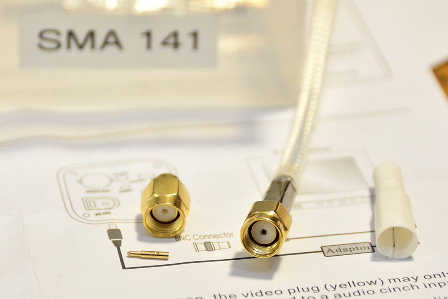
SMA-RP connector is simply cut off, tossed in the bin, and feedline prepared for an SMA (m) connector.

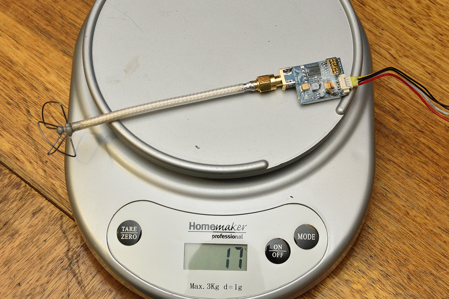
Done!
Aside from avoiding ~ 1dB loss with an adapter that’s not needed, we also save 2 grams!
(Weight with adapter = 19g)
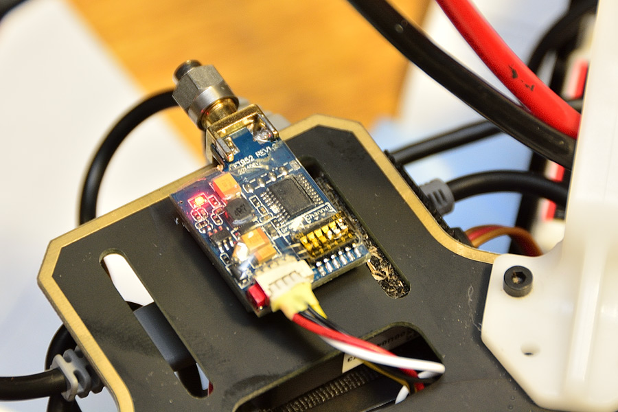
200mW transmitter is now mounted to the underside of an F450 lower board.
(A 50 Ω SMA dummy load was connected to the antenna port during testing)
Don’t ever be fooled into thinking you need a 90° adapter – you don’t.