A reliable 5V power supply is required to power a controller for an Eltek Flatpack2 48/2000 HE rectifier being used as the PSU for a future 23cm 600W LDMOS Power Amplifier project.
Note: Changes have been made since that video was shot, notably a more robust power supply, and many improvements to the GUI.
Cheap 60V to 5V LM2596HVS based step down converters found on eBay out of China are terrible, and the LM2596HVS IC are most likely inferior ‘fakes’.
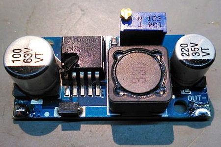
Image source: https://www.eevblog.com/forum/reviews/fake-lm2596hv-again/msg2009078/#msg2009078
So I started looking for an LM2596HVS IC from a reputable supplier, like RS Components.
… but they don’t stock it!
That raised a red flag, so I then researched suitable DC down converter chips that had a genuine high voltage input tolerance.
Enter the Maxim MAX5035, a “1A 76V High efficiency step-down DC-DC converter”, available in an SOIC8 package and with a fixed 5V output voltage variant.
https://au.rs-online.com/web/p/dc-dc-converters/7329614/
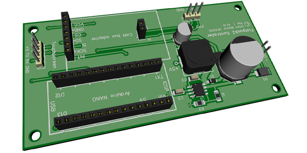
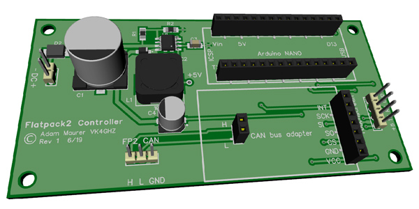
From the datasheet application notes a power supply was designed, and a suitable PCB layout was created that also accommodated the connectivity for the Arduino Nano and the CAN bus adapter all on the one 10 x 5cm PCB.

25-7-2019 Update:
A batch of PCBs arrived weeks ago, so it was time to assemble a board and get it running.
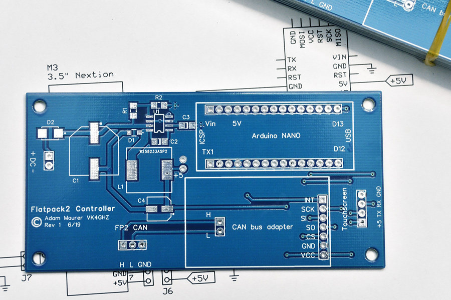
I’m a bit over green solder mask, so blue it was!
There is little point re-inventing the wheel, so instead of replicating the circuitry of an Nano and CAN-bus adapter, cheap and readily available modules simply insert into the controller “main board”.
Incidentally, it would have cost more to purchase the individual parts required to replicate a Nano and CAN-bus adapter.

Above: Mounting arrangement. CAN-bus adapter is upside down to access connectors.
Connecting the Flatpack2 to the outside world is by way of an adapter PCB purchased on eBay.
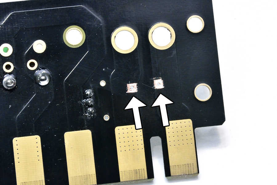
To power the controller board, two 0.9mm holes were drilled so that a suitable connector could be mounted to the PCB.
Solder mask was scraped away, creating two solder pads, for the connector.
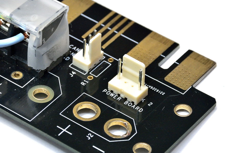
Above: 4-pin polarised 0.1″ pitch connector (with middle two pins removed) has been soldered to the interface PCB.
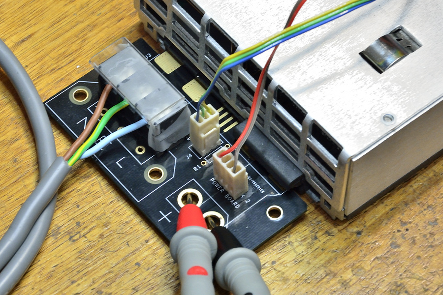
Above: Interface PCB connectivity. Mains, CAN-bus to controller, and power to controller.
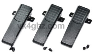
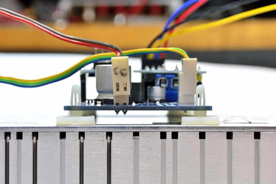
The controller board is mounted to the top face of the Flatpack2 using adhesive PCB supports.
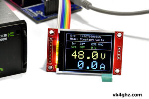
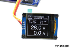
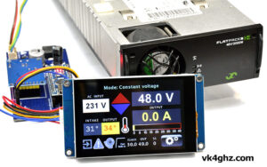
Finished controller in action, with a Nextion 3.5″ (enhanced) touchscreen GUI.
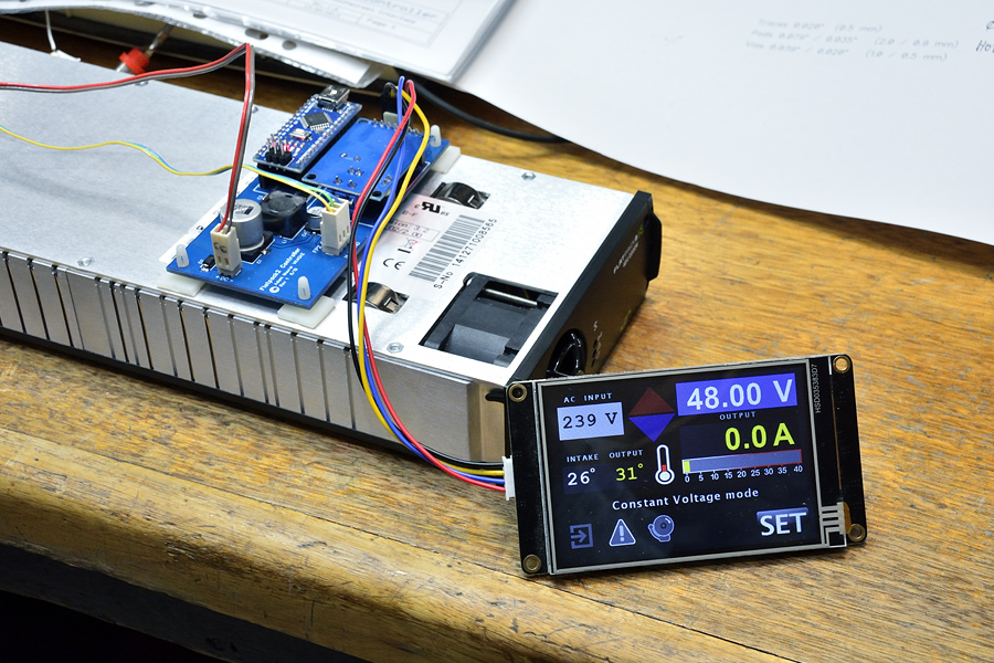
48V (nominal) 2000W PSU and controller ready to integrate into a future 23cm LDMOS Power Amplifier project.
For more information about this project: https://vk4ghz.com/eltek-flatpack2-48v-2000-controller/